 Tinkercaster
At the bench
How to shield a guitar cavity
Copper tape versus conductive paint, how to make every seam conductive, where the single ground connection goes on a Strat pickguard or Tele plate, and what shielding cannot fix.
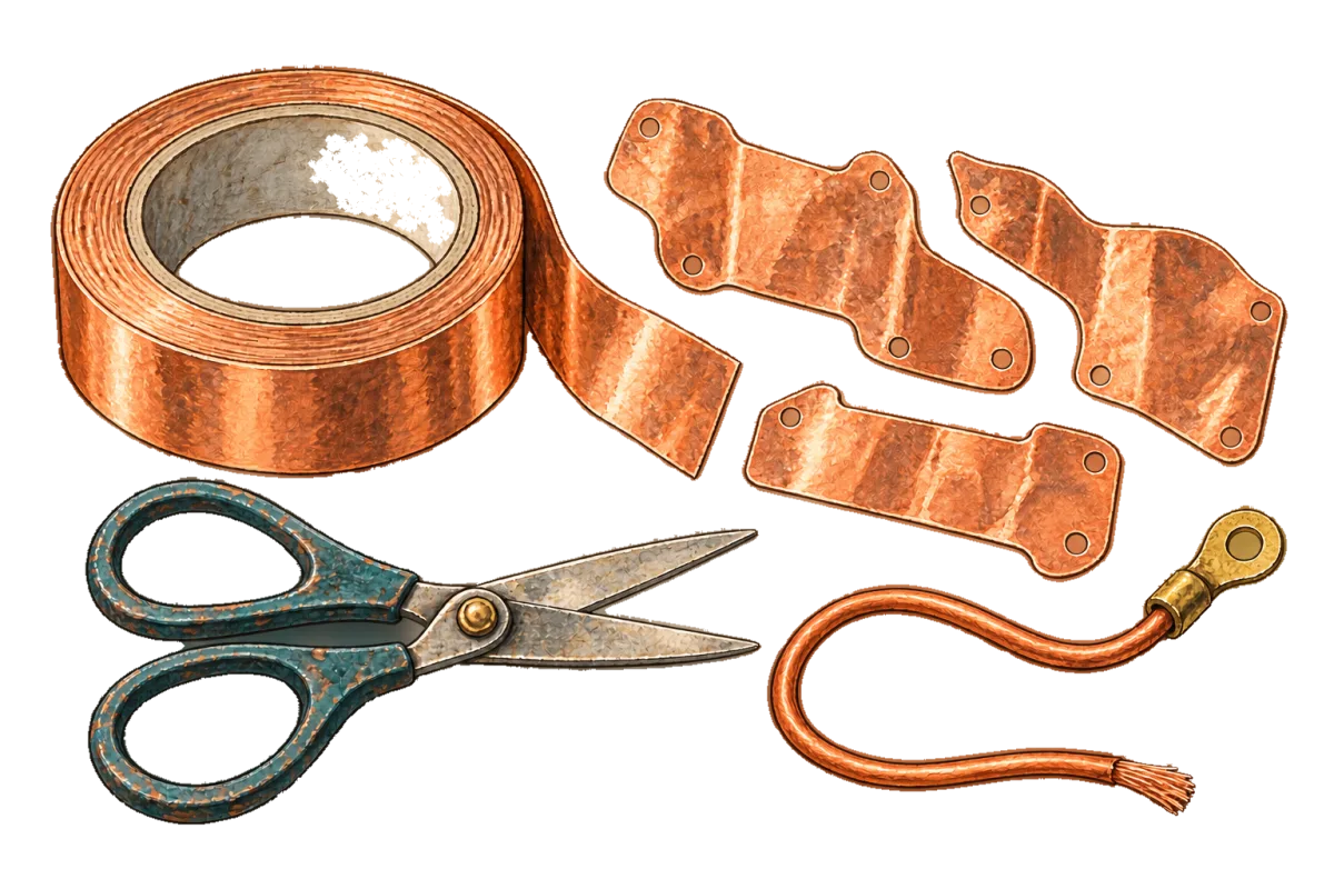
Shielding lines the control and pickup cavities with a conductor, joins every piece of it electrically, and connects the whole lining to the guitar’s ground at one point. Done properly it forms a grounded enclosure around the high-impedance wiring, so electric-field interference lands on the lining and drains to ground instead of coupling into the signal. It reduces buzz and radio pickup. It does not reduce single-coil hum, which is magnetic.
That limit decides whether the job is worth doing. Seymour Duncan says shielding will never get rid of the 60-cycle hum present with single coils, because shielding does not reduce the stray magnetic fields that reach a high-impedance single-coil pickup. If you have not yet separated hum from buzz, do that first with the touch test and meter checks in why is my guitar buzzing.
What the shield does, electrically
Two kinds of interference reach a passive guitar.
| Interference | Coupling | Stopped by a grounded cavity shield? |
|---|---|---|
| Mains hum at 50 or 60 Hz | Magnetic field induces voltage in the pickup coil | No. Only humbucking pickup design cancels it |
| Buzz, hash and radio pickup | Electric field couples through stray capacitance into wiring and coils | Largely, if the shield is continuous and grounded |
The wiring inside a cavity is a set of small antennas at high impedance. Seymour Duncan describes the aim of shielding as enclosing the electronics in a cage that rejects stray radio-frequency interference, so the wiring stops acting as antennae. The cage only works when it is connected to ground. StewMac agrees that a cavity covered in paint or foil but not connected to ground is not doing the job.
What our diagrams show, and what they do not
None of the 330 diagrams in our library draws cavity shielding. The manufacturer sheets they are drawn from show only the circuit. Every drawing does show the ground node the shield must join, which is the part people get wrong.
Seymour Duncan’s standard Strat layout makes the node explicit. Every ground in the circuit ends on the volume pot casing.
Three single coils, five-way, volume and tone, drawn by Tinkercaster from Seymour Duncan sheet 3S_5W_1V_1T. The volume casing is the ground hub.
Parts, connections and bench checks ↗Open interactive diagram ↗The diagram’s ground connections:
| Connection | Role |
|---|---|
| Neck, middle and bridge green (ground) leads → upper solder spot on the volume casing | Coil returns |
| 5-way switch ground pole common (T8) and tags T5, T6, T7 → same spot | Switch ground pole |
| Volume right lug (lug1) → lower solder spot on the casing | Grounded end of the volume track |
| Tone casing upper solder point → volume casing upper solder point | Joins the tone pot to the hub |
| .047 µF cap’s other leg → tone casing | Tone cap ground |
| Bridge ground wire → volume casing upper solder spot | Strings and tremolo |
| Volume casing upper solder spot → jack sleeve | The single ground exit |
On a Strat the pots are bolted through the pickguard. If the underside of the pickguard is foil-lined and touches the pot bushings, every pot casing is also connected to that foil, so the pickguard shield is grounded through the hub without a wire of its own. StewMac’s pickguard foil instructions rely on exactly this: extend the cavity tape or paint onto the top of the body so it touches the shielded pickguard, and the control pots on the pickguard are the ground connection for the whole shield.
This is also why the single ground exit matters. In our library, 251 of the 330 connection lists have exactly one wire ending on the jack sleeve. The shield should join that network once, at the hub, and never add a second path to the sleeve.
Copper tape or conductive paint
| Property | Copper tape | Conductive paint | Aluminium pickguard foil |
|---|---|---|---|
| Example | StewMac conductive copper tape: 1.25 mil, in 2 in, 3/4 in and 1/4 in widths, 180 in rolls | StewMac conductive shielding paint: water-based, graphite and carbon black | StewMac pickguard shielding foil: self-adhesive, 0.003 in |
| Seams | Conductive adhesive makes overlaps continuous (StewMac) | Continuous film, no seams | Overlaps rely on the adhesive |
| Accepts solder | Yes | No | No, per StewMac |
| Grounding method | Solder a wire directly to the tape | Screw a solder lug to the painted wall | Contact with pot bushings or cavity lining |
| Best for | Flat floors and walls of control cavities, pickguards | Tight, deep or irregular routs and drilled holes | Pickguard undersides |
StewMac describes its copper tape as having a conductive adhesive, so overlapped seams are electrically continuous, and a surface that accepts solder. Our catalog lists Fender conductive copper tape as 50 mm copper foil with conductive adhesive, and the StewMac shielding paint in half-pint and one-pint cans; browse the rest in jacks, shielding and ground.
Seymour Duncan’s own walkthrough adds two material points. Aluminium performs better electromagnetically, but copper is preferable for DIY work because it can be soldered. The adhesive’s conductivity also matters, because the pieces must overlap, and if the adhesive were not conductive, every piece would have to be soldered. Not every copper tape on the market has a conductive adhesive, so measure before you trust it.
Lining the cavity with tape
Work on a clean, dry, dust-free cavity with the electronics removed.
- Cut pieces slightly oversize. StewMac’s shielding guide trims tape so it laps up onto the side walls, and overlaps every piece for electrical contact.
- Line the floor, then the walls, pressing each piece down firmly so the adhesive seats fully at the overlaps.
- Carry the lining over the top edge of the cavity and onto the body face where the pickguard or control cover will sit, if the cover is also shielded.
- Cover the pickup routs if you are shielding them, and the channels between cavities if the cover design allows the lining to meet.
- For extra security, tack-solder the seams. StewMac shows soldered seams on a Santana Stratocaster as an optional step for strength and continuity.
- Trim the lining back around the pot and switch mounting holes if the parts mount into the cavity, so no lug or hot wire can touch it.
StewMac’s buzzkill guide notes that most output jack cavities stay unshielded, to avoid an accidental short, with shielded wire carrying the signal instead. StewMac’s grounding guide lists shielding touching a hot connection as one of the common mistakes. A hot lug touching a grounded lining is a dead short to ground: the guitar goes silent or cuts out as parts move.
Using conductive paint
StewMac’s paint instructions call for at least two coats on clean, dry surfaces with 24 hours between coats, stirring before use, and thinning with water if it thickens. Wear goggles and rubber gloves and avoid breathing the vapour; the paint contains 2-butoxyethanol.
Paint will not take solder, so it needs a mechanical ground point. StewMac’s assembly guide screws a piece of brass into the cavity side wall with a small wood screw and solders it to the volume pot casing. The same guide extends the paint over the body top under a Strat pickguard so that the grounded pickguard foil contacts the painted cavity when the pickguard goes on.
Connecting the shield to ground: one path
The rule is Fralin’s: connect everything, but connect it once. Their specific warning is about shielded pickguards: guitars often ship with a shielded pickguard and ground jumpers between the pots, and you do not need both. The shield already joins the pot casings, so the jumpers close a second path and form a loop.
Match the method to the construction:
| Construction | Ground connection for the shield |
|---|---|
| Strat-style, pots on a shielded pickguard | Through the pot bushings touching the pickguard foil, with cavity lining carried up to meet the foil (StewMac) |
| Copper-taped cavity, pots mounted through the body | One short wire from the tape to the volume casing (StewMac: solder the ground wire directly to the foil; if the volume housing contacts the foil, no separate jumper is needed) |
| Painted cavity | A screwed solder lug in the wall, wired once to the volume casing |
| Telecaster metal control plate | The plate itself joins the pots, switch and jack; Fralin says one wire from the volume pot to the jack grounds them |
On a Telecaster the sources differ.
Standard Telecaster wiring, drawn by Tinkercaster from Seymour Duncan sheet Tele_Standard. The source draws the volume-to-tone casing wire dashed.
Parts, connections and bench checks ↗Open interactive diagram ↗Our standard Telecaster drawing follows Seymour Duncan’s sheet: both pickup black leads and the bridge ground wire land on the volume casing, the volume and tone casings are joined by a wire the source draws dashed, and a single wire runs from the tone casing to the jack sleeve. Fralin’s grounding article, discussing a Tele control plate that already connects all the electronics, calls extra jumpers over-grounding and shows a single ground wire from the volume pot to the jack as correct. Both describe the same node. On a metal plate the casing-to-casing wire is electrically redundant, and it is the kind of parallel path Fralin advises against. Our reading of the dashed line is that it marks a connection the plate may already make. Measure it: if the casings already read as connected through the plate, the extra wire adds nothing.
Prove it with a meter
Do this before the electronics go back in, then again with everything assembled. Set the meter to resistance on its lowest range.
- Check the seams by probing across every overlap, piece to piece. Seymour Duncan checked that every piece of copper was electrically connected to every other. A piece that reads open to its neighbour has a non-conductive adhesive or a lifted seam: solder it.
- On paint, probe from the solder lug to the farthest painted point in each cavity. A painted film will not read as low as copper, so compare it against a known-good area rather than expecting zero. StewMac’s instructions give no target figure, and we do not supply one.
- Check the path to ground by probing from the jack sleeve to the lining in each cavity and to the pickguard foil. Fralin’s check reads “0.0” for a solid connection and “0.L” for an open one, and tells you to make sure any shielding or conductive paint has a connection to ground.
- Check for shorts: with the harness installed, probe from the jack tip to the lining. With the volume up you should see the pickup’s resistance, as the bench checks on our diagrams describe for tip to sleeve; with the volume at zero you should see a short, because the wiper is then on the grounded end. A dead short to the lining with the volume up means a hot lug or wire is touching the shield.
The meter technique, including how to read a pickup through the jack, is covered in the multimeter course.
Grounded strings and your safety
Shielding and a bridge ground put more of the guitar’s metal at the amplifier’s ground potential. That is what makes them work, and it is also why your equipment’s grounding matters. Seymour Duncan’s advice is to check the electrical polarity or ground of the systems you are using, particularly between the amplifiers and the PA, and to be especially careful with equipment used on a different mains voltage. They note that some players lift the ground from the strings and cavity, at the cost of more interference, and that some instruments fit a fuse circuit between the strings and the grounded controls. Those are decisions for a qualified tech. The hazard is a faulty amp, and the shielding does not create it.
At the bench, work with the guitar unplugged from any amp, remove any battery from active electronics, and follow the soldering precautions in the soldering cheat sheet and how to solder guitar wiring.
What to expect afterwards
A continuous, grounded shield lowers buzz and radio pickup. StewMac’s buzzkill guide also lists reduced static shock from a shielded pickguard. It will not change the hum a single coil picks up from a transformer, and it will not cure a bad solder joint or a missing bridge ground. If single-coil hum is the problem, the answer is a hum-cancelling design such as the pickups in the stacked hum-cancelling Strat five-way diagram.
Next step
Open the diagram that matches your guitar, for example the Seymour Duncan three single coils, five-way, volume and tone layout, find the ground hub the shield will join, and meter every casing back to the jack sleeve before you line the cavity. The library, the catalog and the courses are free, and so is opening that diagram in the workbench to save and customise your own board. Tinkercaster Pro adds Luthier, who can talk through your ground scheme, and a guided build with meter checks at each step.
References
From the Tinkercaster library
- Three single coils, five-way, volume and tone (Seymour Duncan 3S_5W_1V_1T): volume casing as ground hub
- Standard Telecaster wiring (Seymour Duncan Tele_Standard): casing link drawn dashed, single wire to the sleeve
- Stacked hum-cancelling Strat five-way (DiMarzio)
- Catalog: Fender conductive copper tape, StewMac conductive shielding paint, StewMac shielding paint 1-pint, Jacks, shielding and ground
- Using a multimeter for guitar wiring, Soldering cheat sheet
Manufacturer and technical sources
- Seymour Duncan, Guitar shielding: shielding does not remove 60-cycle single-coil hum, cage rejects RF, aluminium versus copper, conductive adhesive, metering every piece
- Seymour Duncan, My single coil pickups hum really bad in the studio: shielding does not reduce stray magnetic fields
- Seymour Duncan, Safety precautions to isolate electrical shock: check polarity between amps and PA, lifted string grounds, fuse circuits
- StewMac, Conductive copper tape: conductive adhesive, continuous overlaps, accepts solder, dimensions
- StewMac, Pickguard shielding foil: aluminium, will not accept solder, extend lining to meet the pickguard, pots as the ground connection
- StewMac, Conductive shielding paint instructions: two coats, 24 hours between coats, composition, goggles and gloves
- StewMac, Single-coil buzzkill: oversize pieces lapping onto walls, overlaps, optional soldered seams, jack cavity usually unshielded
- StewMac, Understanding guitar wiring part 8: grounding and shielding: shielding must be grounded, shielding touching a hot connection
- StewMac, Electric guitar and bass assembly guide part 4: solder to foil, volume housing contacting foil, brass lug for paint, pickguard foil meets painted cavity
- Fralin Pickups, Understanding guitar grounding and common mistakes: connect once, shielded pickguard plus jumpers is over-grounding, Tele control plate, meter readings, shielding must reach ground