 Tinkercaster
Troubleshooting
Why is my guitar buzzing? (grounding explained)
Separate magnetic single-coil hum from electric-field buzz and intermittent crackle, then prove every ground path to the jack sleeve with a meter, using the checks from our diagrams.
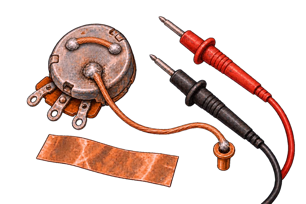
A buzzing guitar usually has one of three problems, each with its own mechanism. Steady 50 or 60 Hz hum is usually a magnetic field inducing voltage in a single-coil pickup. That comes from the pickup itself, and no wiring fault is involved. Fizzy buzz that drops when you touch the strings is electric-field interference, and a working ground drains it. Crackle and dropouts are an intermittent connection. Work out which one you have before you touch the soldering iron, then prove every ground path back to the jack sleeve with a meter.
This article applies to passive electric guitars wired the conventional way: pickups, pots and switch return to ground through the pot casings, a single wire reaches the sleeve of a mono output jack such as a Switchcraft #11, and a separate wire grounds the bridge, tailpiece or tremolo claw. Active pickups use the same ground scheme plus a battery circuit, covered in how to wire a guitar output jack.
Three noises, three mechanisms
| Symptom | Mechanism | What fixes it |
|---|---|---|
| Steady low hum at one pitch, changes as you turn in the room | Mains-frequency magnetic field induces a voltage in the pickup coil | Humbucking pickup design, or reorienting the guitar and amp. Grounding and shielding do not remove it |
| Higher “hash” or buzz, drops sharply when you touch the strings | Electric-field coupling into the coil, wiring and your body | A complete ground network, a grounded bridge, grounded shielding |
| Crackle, pops or dropouts when you move the cable, a knob or the switch | A contact or solder joint that opens and closes | Reflow or replace the joint, jack or part |
Seymour Duncan describes the familiar hum as the 50 or 60 Hz cycle of the mains supply, and notes that a humbucking pickup cancels it at source. DiMarzio draws the line on the other side: humbuckers reduce low-frequency hum but not the higher-frequency noise you get in rooms with fluorescent lights or dimmers, and that higher-frequency noise changes as you move the tone control.
The distinction matters because the fixes do not overlap. Seymour Duncan is explicit that you can shield a guitar as much as you like and it will not reduce the stray magnetic fields that reach a high-impedance single-coil pickup. Rewiring the grounds of a Strat to cure single-coil hum is wasted work.
The touch test, and what it actually proves
Plug in, raise the volume, and let go. Then touch the strings or bridge.
When the noise falls as you touch the strings, the ground is working. Your body is a conductor sitting in the room’s electric field and couples that field into the guitar’s high-impedance circuit. Touching grounded strings ties you to the circuit’s ground, so the interference you were coupling in is shunted away. Fralin puts it this way: when the noise drops on contact, the guitar is grounding you, not the other way round. DiMarzio says the same: with a grounded bridge or tailpiece, most of this noise disappears when either hand touches the strings or bridge.
Read the result this way:
| Result | Likely cause | Next step |
|---|---|---|
| Noise drops on contact | Normal. Bridge ground is intact | Look at the room and the pickups, not the wiring |
| No change, lots of buzz | Strings not grounded | Meter the bridge ground wire |
| Noise gets louder on contact | StewMac lists this as a sign the bridge ground has a problem | Meter the bridge ground and the jack sleeve |
| No change, but hum varies as you rotate the guitar | Magnetic single-coil hum | Not a ground fault |
How our diagrams build the ground network
Every drawing in our library lists the ground connections one by one, so you can see exactly what “grounded” means for that circuit. The pattern is consistent: each pickup’s ground lead lands on a pot casing, the grounded outer lug of each pot is bent onto its own casing, the casings are linked, and one wire runs from that network to the jack sleeve.
Seymour Duncan’s two-humbucker, two-volume, master-tone layout shows the whole chain in 21 listed connections.
Two humbuckers, three-way toggle, two volumes and one tone, drawn by Tinkercaster from Seymour Duncan sheet 2H_3G_2V_1T.
Parts, connections and bench checks ↗Open interactive diagram ↗The ground connections, in the diagram’s own terms:
| Connection | Why it is there |
|---|---|
| Bridge green and bridge bare → bridge volume casing | Returns the bridge humbucker’s coil end and its cover/baseplate shield to ground |
| Neck green and neck bare → neck volume casing | The same for the neck pickup |
| Each volume’s right lug → its own casing | Grounds the end of the volume track, so the wiper can take the signal to zero |
| Toggle ground lug → bridge volume casing | Grounds the switch frame |
| .047 cap → tone casing | The cap’s ground end, so the tone control bleeds treble to ground |
| Bridge volume casing → neck volume casing → tone casing | Links the three casings into one ground |
| Tone casing → jack sleeve | The only ground wire that reaches the jack |
| Bridge ground wire → tone casing | Grounds the strings through the bridge |
This is a daisy chain: casing to casing to casing, then one wire to the sleeve. It is safe because it never closes back on itself. Fralin explains the failure it avoids: grounding a set of pots with wire in a circle forms a one-turn loop that can add noise, and adding jumpers where a shielded pickguard or metal control plate already joins everything is the classic over-grounding mistake. Their rule is “connect everything, but connect it once.” They describe star grounding (every ground to one hub, often the Strat volume pot) as the arrangement that makes a loop hardest to create, and also note that some engineers say it makes no measurable difference. Both layouts work if every part has exactly one path to the sleeve.
Bridge grounds across the library
In our library, 318 of the 330 diagrams draw or list a ground from the bridge, tailpiece or tremolo: all 57 DiMarzio diagrams, 222 of 228 Seymour Duncan and 39 of 45 Tonerider. The other 12 are sheets where the manufacturer’s drawing leaves it off, including the three Live Wire active sets and a Music Man sheet that stops at the preamp input. A passive guitar still needs the wire when its drawing omits it.
Where the wire lands differs by maker. Among diagrams whose connection list names the bridge ground, DiMarzio lands it on the output jack sleeve in 38 diagrams and on a pot casing in 15. Seymour Duncan lands it on a pot casing in 196 and on the sleeve in 2, and Tonerider on a casing in 31 and the sleeve in 5. Electrically these are the same node. The practical difference is where you meter it and which joint carries it: on DiMarzio’s Strat standard three singles five-way sheet the bridge ground goes straight to the output jack sleeve, while Seymour Duncan’s sheet above puts it on the tone casing.
The hardware at the other end varies too:
- On a Strat-style tremolo, StewMac’s Strat harness instructions thread the ground wire into the spring cavity and solder it to the tremolo claw. For a hardtail, the same instructions push back the insulation and clamp the bare wire under the bridge plate, with no solder. Our catalog lists a Fender tremolo claw ground and a Floyd Rose tremolo ground, and uses a generic bridge ground wire wherever a diagram draws the wire without naming hardware.
- On a Telecaster, Seymour Duncan’s four-way Tele sheet lists a bridge plate ground to the volume casing and a separate ground wire for the neck pickup’s metal cover, because on that circuit the neck pickup’s black lead goes to the switch, not to ground. Fralin adds that where the bridge pickup’s screws thread into a grounded steel plate, that can be enough to ground the strings, and warns about stray ground wires trapped under the saddle plate.
Telecaster, two single coils, four-way switch, drawn by Tinkercaster from Seymour Duncan sheet Tele_2S_4B_1V_1T. The neck cover ground and bridge plate ground are listed as connections even though they carry no signal.
Parts, connections and bench checks ↗Open interactive diagram ↗The cover needs that wire because the diagram sends the neck pickup’s black lead to the switch, which grounds it in some positions and uses it as the series link in another, so the lead can no longer be relied on to ground the metal cover. The cover gets its own wire to the volume casing instead; an ungrounded cover over the coil is a conductor floating in the room’s electric field. The full four-position logic is in how to wire a Telecaster 4-way switch.
Cold joints on pot casings
The pot casing is the most common bad ground joint because it is a large piece of metal that pulls heat away from the solder. The joint that results can look attached and still have high resistance, or only make contact when the wire is pressed. StewMac describes cold joints as dull, cracked or blobby. An intermittent casing joint produces exactly the crackle-and-buzz symptom that comes and goes as you move the knob.
The technique and iron temperatures, taken from Kester’s data sheets, are in how to solder guitar wiring, and the soldering cheat sheet summarises them for the bench. Before you pick up the iron: unplug the guitar from the amp, take the battery out of any active electronics, extract the fumes, and wash your hands after handling leaded solder.
Single-coil hum is a pickup property
A single-coil pickup is one coil around a magnet. StewMac calls the coil an antenna that picks up 60 cycle hum. The field comes from transformers and mains wiring. Seymour Duncan notes that hum is much worse near larger amplifiers with large power and output transformers, that CRT monitors radiate interference, and suggests turning the amp to a different angle.
A standard Strat lets you check whether this is what you are hearing. With a reverse-wound, reverse-polarity middle pickup, Seymour Duncan confirms you get hum cancelling in positions 2 and 4 of a five-way. The position map from our three single coils, five-way, volume and tone diagram shows why:
| Position | Pickups | Hum with an RWRP middle |
|---|---|---|
| 1 | Bridge | Single coil, hums |
| 2 | Middle and bridge in parallel | Cancels |
| 3 | Middle | Single coil, hums |
| 4 | Neck and middle in parallel | Cancels |
| 5 | Neck | Single coil, hums |
If positions 2 and 4 are quiet and 1, 3 and 5 hum, the wiring is doing its job. Our diagrams do not state magnet polarity unless the source sheet does, so confirm your middle pickup is RWRP from its maker’s specification. If the hum is unacceptable, the fix is a hum-cancelling pickup such as those in the stacked hum-cancelling Strat five-way diagram. The same logic applies to P-90s, covered in how to wire a P-90.
Prove the ground network with a meter
Do this with the guitar unplugged and the cavity open. You are measuring the drawing’s ground connections against the physical guitar.
Our simplest drawing sets out the target. Tonerider’s one P90 with one volume has four ground connections: the P90’s black lead and bare shield wire to the volume casing, the volume’s right lug bent onto the casing, the casing to the jack sleeve, and the ground wire from the bridge to the casing. Its bench checks read:
- With the volume up, the meter across the jack should read the P90’s resistance.
- The jack sleeve should read continuity to the volume casing and the bridge ground wire.
One P90 with one volume, drawn by Tinkercaster from Tonerider sheet 1_P90_1V.
Parts, connections and bench checks ↗Open interactive diagram ↗Scale that up to any guitar:
- Set the meter to resistance on its lowest range. Fralin recommends resistance over the continuity beeper because a cold joint can still beep while showing a raised reading.
- Put one probe on the jack’s sleeve lug. That is the reference your amp sees through the cable.
- Touch the other probe to every part that should be grounded: each pot casing, the switch frame, the strings, the bridge or claw, pickup covers and baseplates, and any shielding.
- Fralin reads “0.0” as a solid connection and “0.L” as a broken one. StewMac expects continuity or a very low resistance. A reading that is higher than the others, or that moves when you press on a joint, is a cold joint.
Then run the signal checks from the diagram. Many of our drawings include this one: with the volume at zero, tip and sleeve should read as a short. At zero the volume’s wiper sits on the grounded end of the track, so a short across the jack proves the tip wire, the wiper and the ground return in one reading. In our library, 71 diagrams carry that check.
If every ground reads correctly and the guitar still buzzes, Fralin’s next suspect is the cable, so check that its sleeve is connected. After that, suspect the room.
Rule out the room
Take the same guitar, cable and amp into another room. Switch off dimmers and fluorescent fittings, which DiMarzio names as sources of the higher-frequency noise. Rotate the guitar through a full turn in front of the amp. Magnetic hum rises and falls with angle; a ground fault does not.
If the remaining noise is electric-field buzz and your cavities are bare, how to shield a guitar cavity covers shielding and how to ground it without creating a second path.
Next step
Open the diagram closest to your guitar, for example the Seymour Duncan two-humbucker, two-volume, master-tone layout, and tick off each ground connection against your cavity with the meter. The library, the catalog and the multimeter course are free, and so is opening that diagram in the workbench to save and customise your own board. With Tinkercaster Pro you can also ask Luthier about a ground you are unsure of and follow a guided build that records each meter reading as you go.
References
From the Tinkercaster library
- Two humbuckers with a three-way toggle, two volumes and one tone (Seymour Duncan 2H_3G_2V_1T): ground chain and bridge ground to tone casing
- Telecaster, two single coils, four-way, one volume, one tone: neck cover ground and bridge plate ground
- One P90 with one volume (Tonerider 1_P90_1V): four ground connections and sleeve continuity check
- Strat standard three singles five-way (DiMarzio): bridge ground to jack sleeve
- Three single coils, five-way, volume and tone (Seymour Duncan 3S_5W_1V_1T): five-way position map
- Stacked hum-cancelling Strat five-way (DiMarzio)
- Catalog: Switchcraft #11, bridge ground wire, Fender tremolo claw ground, Floyd Rose tremolo ground
- Using a multimeter for guitar wiring, The wiring course (grounding chapter), Soldering cheat sheet
Manufacturer and technical sources
- Seymour Duncan, Background noise: closing the loop: 50/60 Hz mains hum, humbuckers cancel it, body as antenna, bridge must be grounded
- DiMarzio, noise when I take my hand off the strings: humbuckers reduce low-frequency hum but not higher-frequency noise; fluorescent lights and dimmers; grounded bridge removes most of it on contact
- Fralin Pickups, Understanding guitar grounding and common mistakes: ground once, one-turn loop, over-grounding with shielded pickguards, star grounding, Tele bridge plate, meter procedure, resistance versus continuity, check the cable
- StewMac, Understanding guitar wiring part 8: grounding and shielding: bridge ground faults, noise worse when touching strings, cold joint appearance, low resistance reading
- StewMac, Single-coil buzzkill: the single-coil pickup picks up 60 cycle hum
- Seymour Duncan, My single coil pickups hum really bad in the studio: shielding does not reduce stray magnetic fields; large transformers; CRT monitors; amp angle
- Seymour Duncan, Pickup polarity and phase made simple: RWRP middle gives hum cancelling in positions 2 and 4
- StewMac, Strat wiring harness installation instructions (PDF): ground wire soldered to the tremolo claw, or clamped under a hardtail bridge