 Tinkercaster
Troubleshooting
How to fix a dead pickup (diagnostic guide)
Isolate a silent pickup to the coil, switch, pot or jack with the meter readings our wiring diagrams specify, maker DC resistance specs, series link checks and active battery tests.
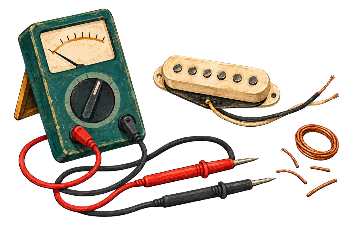
When a pickup goes silent, the coil itself is rarely the problem. The usual fault is an open or shorted connection somewhere between the coil and the jack tip: the pickup’s lead, a switch contact, the volume pot, the jack, or the ground path back to the sleeve. You find it with two resistance readings. The first is across the jack, in each switch position, which tells you whether the signal path is complete. The second is at the pickup’s own leads, which tells you whether the coil is intact. Compare both with the maker’s DC resistance spec, and the fault falls into one of a few places.
Our library is built for this test. In the wiring diagram library, 218 of the 330 diagrams end with a “Check before plugging in” section: the readings a correctly wired harness should give. This guide uses three of them, a passive single-coil Tele, a two-humbucker toggle guitar and an active set, to show which reading isolates which part.
The multimeter course covers meter setup, continuity mapping, measuring components, output jack tests and fault finding in full.
Before you measure
Unplug the guitar from the amp. On an active guitar, take the battery out before you unsolder anything. Resistance readings must be taken on an unpowered circuit: Fluke’s guide to measuring resistance says to switch off power first, and warns that touching the metal probe tips puts your body in parallel with the part and skews the reading. DiMarzio’s FAQ adds that pickups should be measured at room temperature, without your fingers on the leads.
Know what your meter shows for an open circuit. On a Fluke, and most digital meters, it is OL: the resistance is beyond the meter’s range.
A quick go or no-go check before you open the guitar: plug in, keep the amp quiet, select the suspect pickup with its volume up, and tap a pole piece lightly with a steel screwdriver. A connected pickup gives a clear knock. Silence means the signal isn’t reaching the amp, and the meter finds where it stops.
Know the number you are measuring against
A resistance reading only means something against the spec for your exact pickup. DiMarzio’s FAQ says readings should fall between about 1k and 20k, and that a reading of zero or infinite ohms indicates a problem. Seymour Duncan’s pickup resistance article shows how wide the real spread is, from Custom Flat Strat single coils at 12.27k to 13.3k to a Vintage Stack at close to 20k, and stresses that DC resistance is not output.
Our catalog records maker specs where they are published:
| Pickup | DC resistance (catalog) |
|---|---|
| DiMarzio Twang King Neck DP172 | 6.22k |
| DiMarzio Twang King Bridge DP173 | 8.07k |
| DiMarzio PAF 36th Anniversary Neck DP103 | 7.31k |
| Seymour Duncan ’59 Model SH-1 Neck | 7.43k |
| Seymour Duncan JB Model SH-4 | 16.4k |
Specs aren’t always consistent between a maker’s own sources. Our catalog lists the JB at 16.4k, while Seymour Duncan’s current JB Model product page states 16.6k. A reading near either is a healthy coil. The readings that point to a fault are OL, a reading near zero, or one far off both.
The diagrams themselves mostly don’t give numeric readings: 199 of them state that pickup resistance is not specified, so the checks describe what should connect rather than a figure. You supply the figure from the maker’s spec.
Case one: a passive Tele, two single coils
The DiMarzio Standard Tele wiring is drawn with a Twang King neck (DP172) and bridge (DP173), a three-way Tele switch (EP1105, drawn with a CRL 3-Way Blade as the compatible example), a 250K custom-taper volume, a 250K custom-taper tone, a .022µF capacitor and a Switchcraft two-conductor output jack.
DiMarzio Standard Tele wiring, drawn by Tinkercaster from DiMarzio's diagram Tele® Standard Wiring, revision 1.
Parts, connections and bench checks ↗Open interactive diagram ↗The signal path, in the diagram’s words: each pickup’s WHITE goes to the switch (neck to the top-row first lug, bridge to the bottom-row fourth lug); three jumpers chain the switch’s output lugs to the volume bottom lug; the volume middle lug goes to the jack tip. The ground path: each pickup’s BLACK and GRAY go to the volume casing, the volume top lug is wired to the casing and on to the tone casing, and the tone casing runs to the jack sleeve along with the bridge ground.
Its switching table and bench checks:
| Position | What reaches the output | Diagram’s bench check |
|---|---|---|
| 1: neck | Twang King neck DP172 | Continuity from jack tip to sleeve through the neck pickup only |
| 2: neck + bridge | Neck and bridge in parallel | |
| 3: bridge | Twang King bridge DP173 | Continuity through the bridge pickup only |
| Any, volume at zero | Nothing | Tip and sleeve read as a short in every position |
The catalog specs give you numbers to expect. With the volume up full, the meter across the jack sees the pickup in parallel with the 250k volume track. The capacitor blocks DC, so the tone circuit doesn’t show up. So expect roughly 6.1k in position 1 (6.22k in parallel with 250k), roughly 7.8k in position 3, and roughly 3.5k in position 2, where the two pickups are also in parallel with each other. We worked those figures out from the published DCRs. DiMarzio’s sheet doesn’t print them, and your pickups will vary slightly.
Now read the fault from the pattern:
| Reading across the jack | Where the fault is |
|---|---|
| Position 1 normal, position 3 OL | Bridge side only: the bridge pickup, its WHITE to the switch, its BLACK to the volume casing, or its switch contact |
| Position 3 normal, position 1 OL | Neck side only, the same list for the neck |
| Position 2 reads the same as one pickup alone | The other pickup’s switch contact in the middle position |
| OL in every position | The shared path: switch jumpers, switch output to volume bottom lug, volume middle lug to jack tip, the casing ground chain to the sleeve, or the jack |
| Near zero in every position, volume full | Hot shorted to ground: at the jack, the volume, or a lead touching a grounded surface |
| Pickups read correctly, but volume at zero does not short | The volume top lug to casing joint |
If a pickup’s side reads OL, measure the pickup on its own. Unsolder its hot lead (the WHITE here) and measure WHITE to BLACK. DiMarzio’s instruction for single coils is to measure between the two leads, usually black and white, and ignore any ground wire. If the coil reads its spec, the fault is in the joint or the switch. If it reads OL, the break is in the pickup.
Case two: two humbuckers on a toggle
The Tonerider two humbuckers, three-way toggle, two volumes and one tone uses two four-conductor humbuckers in DiMarzio colours, each through its own 500k volume (CTS 500k Audio Pot as the example), a Switchcraft 3-Way Toggle, a 500k master tone with a .022µF capacitor, and a Switchcraft #11 jack.
Tonerider two humbuckers, three-way toggle, two volumes and one tone, drawn by Tinkercaster from Tonerider sheet Tonerider_HH_2vol1ton.
Parts, connections and bench checks ↗Open interactive diagram ↗Each pickup’s red goes to its volume’s left lug (input); its green and bare go to that volume’s casing; its black and white are soldered together and insulated. The volume middle lugs go to the toggle’s neck and bridge lugs, and the toggle middle lug runs through the master tone’s right lug to the jack tip.
| Toggle position | What reaches the output |
|---|---|
| Neck | Neck pickup, both coils |
| Both | Neck and bridge, both coils, in parallel |
| Bridge | Bridge pickup, both coils |
The diagram’s checks: in each toggle position the meter across the jack should read the selected pickup, or both in parallel in the middle; with both pickups selected, turning one volume fully down should mute the whole output; and each taped black and white joint should read open to ground.
That second check catches a common false alarm. In this layout, a volume at zero puts its middle lug at ground. In the middle position the toggle joins both volume middle lugs to the output, so one volume at zero shorts the whole guitar. A “dead” guitar in the middle position with one volume down is behaving as drawn.
The third check is the series link. Black and white are the inner ends of the two coils. If that joint touches ground, one coil is shorted out and the pickup drops to single-coil level. If the joint has broken open, the path from the red lead to ground through the two coils is interrupted and the pickup is silent. Measure the pickup at its leads to tell which: red to green should read the full spec; if it is OL, measure each coil separately.
Which pair forms the series link depends on the maker, and this is where rewires go wrong:
| Maker | Hot | Series link | Ground | Measure each coil |
|---|---|---|---|---|
| DiMarzio (4-conductor instructions) | Red | Black and white, soldered and taped | Green and bare | Black to red, then white to green |
| Seymour Duncan (humbucker internals) | Black | Red and white | Green and bare | Black to white (north coil), red to green (south coil) |
Seymour Duncan’s multimeter pickup test says each coil should read roughly half of the full pickup’s rating. Our library reflects the split: 21 Seymour Duncan diagrams check a taped red and white joint, and 13 DiMarzio and Tonerider diagrams check a taped black and white one. Wire a Seymour Duncan pickup from a DiMarzio-colour drawing and you join the wrong pair. The Seymour Duncan wire colours guide and our article on Gibson vs Fender pickup wire colour codes cover the naming across brands. If the pickup is on a coil split, see the coil split wiring diagram article: the split switch grounds the series link deliberately in one position, and a miswired switch can ground it all the time.
Case three: active pickups
The passive resistance checks above don’t apply in the same way to active pickups. The jack sees the output of an onboard preamp, and the preamp needs power, so check the power first.
The three Live Wire active singles, five-way blade and volume diagram shows the usual arrangement: three Live Wire actives, an Oak Grigsby-type five-way, a 100k master volume, a Switchcraft #12B stereo jack and two 9-volt batteries in series. All three red pickup leads join the positive side of the batteries; battery 1’s black lead goes to the jack’s ring.
Seymour Duncan three Live Wire active singles, five-way blade and volume, drawn by Tinkercaster from Seymour Duncan sheet 3aS_5W_1V.
Parts, connections and bench checks ↗Open interactive diagram ↗The stereo jack is the power switch. Seymour Duncan explains that active pickups use a stereo jack as a switch for the battery, and our catalog entry for the #12B describes it: the ring contact closes the battery negative to ground only while a mono plug is inserted. The diagram’s checks follow from this. With no plug in, the battery negative should read open to ground. With a plug in, the ring should connect it to the sleeve, and the joined red leads should read the battery positive (the two batteries in series) against ground.
So, for an active guitar that has gone silent: measure the battery on DC volts; check the clip leads; confirm the ring closes to ground with a mono plug inserted; and compare the jack wiring with the diagram. A mono jack fitted in place of the stereo one, or the battery black lead on the sleeve instead of the ring, leaves the preamp without a ground return. The same logic applies to the one Blackout active humbucker with volume diagram, which uses a 25K volume and a #12B stereo jack.
Shorts, and what can be repaired
If readings show a short from hot to ground, look at the physical routing. StewMac’s short circuit troubleshooting names the usual causes: pickup leads left too long, folded into the cavity and touching a live lug; a single strand of braided shield touching the hot; and hot lugs pressed against conductive paint or copper tape. Trim leads to length, dress the braid back, and check clearance around every hot lug. If you have just shielded the cavity, how to shield a guitar cavity explains where that goes wrong.
If the pickup reads open at its own leads, check whether the break is in the lead or the coil. Where the lead’s joints to the coil are exposed, as on many single coils, measure directly at them; if the coil reads its spec there, the lead or its joint has failed and can be resoldered or replaced. If the coil itself is open, the fine magnet wire has broken and the pickup needs a rewind or replacement. StewMac’s undead Strat pickup case shows a coil whose insulation had cracked internally and shorted, and the fix was a full rewind. Don’t unwrap a humbucker’s coils to look for the break; that is work for the maker or a pickup winder.
Resoldered a joint? How to solder guitar wiring covers pot-casing grounds, switch lug jumpers and insulated series links, and the soldering cheat sheet is the bench reference.
Next step
Open the diagram that matches your guitar, for example the DiMarzio Standard Tele wiring, and run its “Check before plugging in” readings with the pickup specs from the catalog. The library, catalog, courses and cheat sheet are free, and so is opening the diagram in the workbench to save and customise the board to match what is actually in your guitar. With Tinkercaster Pro, you can also ask Luthier about a reading that doesn’t fit and follow a guided build that records your meter readings at each checkpoint.
References
From the Tinkercaster library
- DiMarzio Standard Tele wiring: parts, connections, switching table and bench checks for case one
- Tonerider two humbuckers, three-way toggle, two volumes and one tone: series link check and the one-volume-mutes-all behaviour
- Seymour Duncan three Live Wire active singles, five-way blade and volume: stereo jack battery switching checks
- Seymour Duncan one Blackout active humbucker with volume: active humbucker with a 25K volume and stereo jack
- Catalog: DP172, DP173, DP103, SH-1 Neck, SH-4 JB, Switchcraft #12B, Switchcraft #11, Switchcraft 3-Way Toggle, CRL 3-Way Blade, CTS 500k Audio Pot
- Seymour Duncan wire colours guide, multimeter course, soldering cheat sheet
Manufacturer and technical sources
- DiMarzio FAQ: 1k to 20k measurement range, which leads to measure on single-coil and four-conductor pickups, room temperature, zero or infinite readings indicate a problem
- DiMarzio: how do I connect a 4-conductor pickup?: red hot, black and white series link, green and bare to ground
- Seymour Duncan: humbucker internals explored: black hot, red and white series link, green and bare to ground
- Seymour Duncan: how to test guitar pickups with a multimeter: per-coil measurement, each coil roughly half the full rating
- Seymour Duncan: pickup resistance vs output: DCR examples, DCR is not output
- Seymour Duncan JB Model: 16.6k DCR as currently published
- Seymour Duncan: active and passive in the same guitar: stereo jack as the battery switch for active pickups
- StewMac: no sound from your guitar? Short circuits: long leads, stray shield strands and hot lugs against shielding
- StewMac: conquering an undead Strat pickup: internal coil short requiring a rewind
- Fluke: how to measure resistance: OL display, measure unpowered, body contact skews readings