 Tinkercaster
Wiring ideas
Coil split wiring diagram (humbucker)
How a humbucker coil split works, lug by lug on a push/pull, from Seymour Duncan, Tonerider and DiMarzio sheets: which coil each maker keeps, split vs tap, partial splits and meter checks.
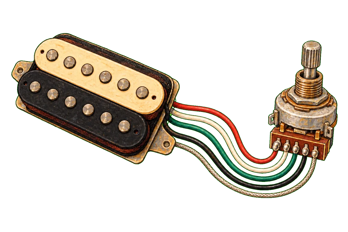
A coil split connects a humbucker’s series link, the joint between its two coils, to ground through a switch. With the link grounded, the coil between the link and the pickup’s ground wire has ground at both ends and contributes nothing. The coil between the hot wire and the link carries the signal on its own. Open the switch and the link floats again, so both coils run in series as a humbucker. The circuit needs a 4-conductor humbucker, because only then does the series link leave the pickup as its own pair of wires.
This article works through the split as three manufacturers draw it, using our own drawings of their sheets. It names each lug the way the drawing does and compares which coil each maker keeps.
How common splits are in our library
Of the 330 diagrams in our library, 97 have a split in their title or specification line: 80 from Seymour Duncan sheets, 12 from Tonerider and 5 from DiMarzio. 45 of those 97 use a 500k push/pull DPDT pot as the switch. Others use mini toggles, 5-way blade wiring that splits automatically in certain positions, or a pot, as in Seymour Duncan’s spin-a-split drawing below.
Colour codes: which pair is the series link
The series link is a different pair of colours for each maker. Putting the wrong pair on the switch is the most common reason a split does nothing, or grounds the hot and silences the pickup.
| Maker | Hot | Ground | Series link, to the switch | Coil the sheet keeps when split |
|---|---|---|---|---|
| Seymour Duncan | Black | Green and bare | Red and white | Slug coil |
| Tonerider (AC and H series) | Red | Green and bare | Black and white | Slug coil (“UP: Split (Slug Coil)”) |
| DiMarzio | Red | Green and bare | Black and white | The red/black (north) coil in standard wiring |
Sources: Seymour Duncan’s humbucker internals article states that grounding the red and white leaves the screw coil with no effect on the sound. Tonerider’s 1 humbucker, 1 volume (push-pull split), 1 tone sheet prints “UP: Split (Slug Coil), DOWN: Humbucker”. DiMarzio’s 4-conductor pickup instructions label the north coil red/black and the south coil green/white, with black and white as the series link. DiMarzio also warns that other brands may use the same colours with different connections. For other makes, see the Seymour Duncan wire colour guide and Gibson vs Fender pickup wire colour codes.
For a split, leave the series link untaped: it stays joined and runs to the switch. The hot and ground wires stay where they were in the plain humbucker circuit.
Walkthrough: one humbucker, push/pull volume split, one tone (Seymour Duncan)
Our drawing of Seymour Duncan sheet 1H_1VppSPL_1T is the reference circuit. It uses only one side of the push/pull switch.
One humbucker with a push/pull coil split, drawn by Tinkercaster from Seymour Duncan diagram 1H_1VppSPL_1T.
Parts, connections and bench checks ↗Open interactive diagram ↗The diagram lists these parts and values: a four-conductor bridge humbucker in Seymour Duncan colours, a 500k push/pull volume (compatible example: a 500k push/pull DPDT such as the CTS 500k Push-Pull DPDT), a 500k tone (CTS 500k Audio Pot), a .047 µF capacitor (Orange Drop .047µF) and an output jack (Switchcraft #11). The original is at seymourduncan.com.
The connections, grouped by function:
The split
- Pickup white → Push/pull middle left lug, and Pickup red → Push/pull middle left lug. The series link lands on the switch common of one pole.
- Push/pull bottom left lug → Volume casing. The throw nearest the pot is grounded. When the switch connects the common to this lug, the series link is grounded.
- The other three switch lugs stay empty.
Signal path
- Pickup black → Volume left lug (input).
- Volume middle lug → Jack tip.
- Volume left lug → Tone left lug. Tone middle lug → .047 cap. .047 cap → Tone casing.
Ground network
- Pickup green and bare → Volume casing. Volume right lug → Volume casing (lug bent onto the casing).
- Volume casing → Tone casing. Tone casing → Jack sleeve. Bridge ground wire → Volume casing.
What each position does:
| Knob | Result | Why |
|---|---|---|
| Pushed down | Full humbucker, both coils in series | The coil link floats |
| Pulled up | Single coil | The coil link is grounded |
The Seymour Duncan sheet does not state which knob position splits. Our drawing follows the usual push/pull behaviour, where pulling the knob joins each middle (common) lug to the lug nearest the pot, and says so in its notes. The catalog’s CTS 500k Push-Pull DPDT lists each pole as up, common and down tags (sw1 to sw3 and sw4 to sw6). Confirm which throw your switch closes when pulled with a continuity check before soldering the link. Seymour Duncan’s on-on and on-off-on DPDT article confirms that the switch built into a push/pull pot is an on-on DPDT, which makes a connection in both positions.
Bench checks from the drawing:
| Check | Expected | Failure it reveals |
|---|---|---|
| Knob down, tip to sleeve | The full humbucker’s resistance | Open: broken hot or ground. Low: the link is touching ground |
| Knob up, tip to sleeve | Drops to roughly one coil’s resistance | No change: the link is not reaching ground. Near zero: you grounded the hot, not the link |
| Volume at zero, both knob positions | A short | Not a short: the volume’s ground lug is not grounded |
The two coils in a humbucker are not always wound identically, so do not expect exactly half the full reading. Our drawings give no numbers because the sheets give none. Use the maker’s published resistance for your model.
The same job on a Tonerider sheet
Tonerider draws the identical circuit with its own colours and a smaller capacitor.
One humbucker, push-pull split volume and one tone, drawn by Tinkercaster from Tonerider diagram 1_HB_1_Vpp_1T.
Parts, connections and bench checks ↗Open interactive diagram ↗| Job | Seymour Duncan 1H_1VppSPL_1T | Tonerider 1_HB_1_Vpp_1T |
|---|---|---|
| Series link to the push/pull left middle lug | Red and white | Black and white |
| Hot to Volume left lug (input) | Black | Red |
| Grounded throw | Bottom left lug, nearest the pot | Left column bottom lug, nearest the pot |
| Tone capacitor | .047 µF | .022 µF (Orange Drop .022µF) |
| Pots | 500k push/pull volume, 500k tone | 500kA push-pull volume, 500kA tone |
| Split position | Not stated on the sheet | “UP: Split (Slug Coil)” |
Five Tonerider drawings in our library label the pulled position “Split (Slug Coil)” or “Split (Slug Coils)”. The capacitor difference is consistent across the library. Of the diagrams that use a 22 nF or 47 nF capacitor, Seymour Duncan drawings use 47 nF in 136 files and 22 nF in 11, while Tonerider uses 22 nF in 38 and 47 nF in 1.
Choosing the coil: DiMarzio’s Les Paul split
Grounding the link always keeps the coil on the hot side. To keep the other coil, you change which end of the pickup is hot, or you connect the link to hot instead of ground, which shorts the hot-side coil. Seymour Duncan’s DPDT article uses the second approach with an on-off-on switch. With the switch in the middle, the link is unconnected and the pickup is a full humbucker. The two ends each select one coil.
DiMarzio’s Les Paul Coil Split sheet does this per pickup. Its caption reads “Push/pull splits to the north coil on the bridge and the south on the neck.”
Les Paul coil split (master tone push/pull), drawn by Tinkercaster from DiMarzio diagram Les Paul Coil Split Wiring.
Parts, connections and bench checks ↗Open interactive diagram ↗The sheet specifies EP1201 500K custom-taper pots for both volumes and the bridge tone, an EP1201PP 500K push/pull for the neck tone (labelled “Neck tone, pull: coil split”), two .022 µF EP1022 capacitors and a Switchcraft EP1101 or EP1102 toggle. One push/pull grounds the series links of both pickups. The neck pickup’s leads are wired so that the coil that remains is the south coil, while the bridge keeps its north coil. In our drawing the neck tone’s push/pull grounds both links. The split positions are marked as not engine-checked, so that drawing’s switching comes from the sheet and has not been simulated by us.
Reversing which end of one pickup is hot also reverses its phase relative to the other pickup. DiMarzio’s 4-conductor instructions describe an out-of-phase pair as sounding “weak and thin” when both are on. If you change the coil choice on one pickup of a two-pickup guitar, check the middle position by ear afterwards. The same instructions add that when a phase switch is combined with a single-coil switch, the phase switch position decides which coil is turned off.
Splitting two pickups at once
A push/pull has two independent poles, so one knob can split two humbuckers. Our drawing of Seymour Duncan sheet 2H_3G_1VppSPL, two humbuckers with a three-way toggle and a push/pull split volume, puts the bridge red and white on the split switch’s left middle lug and the neck red and white on the right middle lug. It jumpers the two bottom lugs together and wires them to the volume casing.
| Toggle | Knob down | Knob pulled |
|---|---|---|
| Neck | Neck humbucker, both coils | Neck, split to one coil |
| Both | Both humbuckers in parallel | Both split, in parallel |
| Bridge | Bridge humbucker, both coils | Bridge, split to one coil |
Its checks add one line to the single-pickup set: with the knob up, each toggle position’s reading drops to roughly one coil. For independent splits, one per pickup, see two humbuckers with a three-way toggle and two push/pull split volumes. The base toggle circuit is covered in how to wire a humbucker to a 3-way toggle.
Push/pull, mini toggle or on-on-on
The switch only has to open and close the path from the series link to ground. DiMarzio’s instructions say a DPDT or a simpler single-pole, double-throw switch will do for single-coil switching.
| Switch | Catalog part | What it gives you |
|---|---|---|
| Push/pull pot, on-on DPDT | CTS 500k Push-Pull DPDT | Humbucker and split, no extra hole |
| Mini toggle, on-on DPDT | Switchcraft Mini toggle DPDT on-on | Humbucker and split |
| Mini toggle, on-off-on DPDT | DPDT Mini-Toggle (on-off-on) | One coil, humbucker, the other coil (per Seymour Duncan’s DPDT article) |
| Mini toggle, on-on-on DPDT | DPDT Mini-Toggle (on-on-on) | Series, split and parallel, depending on the sheet |
DiMarzio’s instructions describe using its EP1108 on-on-on so the two outer positions are series and parallel and the centre is single coil. Seymour Duncan’s version is in the library as one humbucker, volume, mini-toggle series/split/parallel, drawn with series up, split in the middle and parallel down. The plain two-position toggle version is one humbucker, volume, mini-toggle coil split.
Split is not tap, and split is not parallel
Seymour Duncan’s article on coil tapping separates the two. Coil splitting shuts off one coil of a humbucker. Coil tapping uses a wire that leaves a coil partway through its windings, short of the full amount. A tap only exists if the pickup was wound with that extra lead, and the tapped pickups in Seymour Duncan’s article are single coils. Our library draws tapped circuits separately, for example the Telecaster with two tapped single coils and a push/pull tap volume.
DiMarzio’s instructions also separate parallel wiring from a split: parallel wiring is not the same as turning off a coil, and it cancels hum where a split does not. Series vs parallel wiring and our series, split and parallel guide cover that switch.
Why split mode hums
A humbucker cancels hum because its two coils pick up interference in opposite polarity and the two signals combine, as Seymour Duncan’s humbucker internals article explains. Split the pickup and one coil remains, so there is nothing to cancel against. DiMarzio’s instructions say that turning off a coil means the pickup is no longer humbucking and no longer cancels hum. Expect single-coil hum in split mode. If the full humbucker setting also hums, the cause is grounding or shielding, which the split does not change. See why is my guitar buzzing and how to shield a guitar cavity.
Partial splits: the spin-a-split
A partial split grounds the series link through a resistance instead of a wire, so the second coil still contributes something. Seymour Duncan’s sheet 2H_3G_2V_2SSPL does this with a pot in place of each tone control.
Two humbuckers with a three-way toggle, two volumes and two spin-a-split controls, drawn by Tinkercaster from Seymour Duncan diagram 2H_3G_2V_2SSPL.
Parts, connections and bench checks ↗Open interactive diagram ↗In our drawing, each pickup’s joined red and white go to the middle lug of a 500k pot (labelled “Bridge tone 500k” and “Neck tone 500k”, with no capacitor). That pot’s left lug is soldered to its casing and the other outer lug is left empty. The pot is therefore a variable resistor from the series link to ground. The drawing’s checks state the range. With a spin-a-split turned fully down, its pickup’s red and white read as a short to ground (a single coil). Turned fully up, they read about 500k to ground, which leaves the humbucker effectively intact.
We found no manufacturer sheet for these pickups that specifies a fixed resistor for a partial split, so this article does not recommend a value. The spin-a-split lets you find the setting by ear, and the pot’s travel covers the whole range from a full split to an effectively intact humbucker.
At the bench
Push/pull switch lugs are small and close together, so a bridged lug is a common fault. DiMarzio’s instructions recommend a fine-tip iron of 25 to 45 watts with thin rosin-core solder, and ask for clean joints on miniature switches to avoid shorts and switch damage. Never solder with the guitar plugged into an amp. Kester’s safety data sheet for its leaded solder wire says to avoid breathing fumes, ensure adequate ventilation and wash thoroughly after handling. Keep the soldering cheat sheet beside you.
Next step
Open one humbucker with a push/pull coil split, or its Tonerider equivalent if your pickup uses red as hot, and check the colour table against your pickup’s own sheet. The library, catalog and courses are free. To move the split to another knob, split two pickups independently or add a phase switch, open the diagram in the workbench, where saving and customising the board is free too. Tinkercaster Pro adds Luthier, who can explain what a connection does (with a usage limit), and a guided build with meter checkpoints. The coil splitting guide, the push/pull switch guide and the controls and switching course go further.
References
From the Tinkercaster library
- One humbucker with a push/pull coil split (Seymour Duncan 1H_1VppSPL_1T)
- One humbucker, push-pull split volume and one tone (Tonerider 1_HB_1_Vpp_1T)
- Les Paul coil split (master tone push/pull) (DiMarzio Les Paul Coil Split Wiring)
- Two humbuckers with a three-way toggle and a push/pull split volume (Seymour Duncan 2H_3G_1VppSPL)
- Two humbuckers with a three-way toggle and two push/pull split volumes
- Two humbuckers with a three-way toggle, two volumes and two spin-a-split controls (Seymour Duncan 2H_3G_2V_2SSPL)
- One humbucker, volume, mini-toggle series/split/parallel and one humbucker, volume, mini-toggle coil split
- Telecaster with two tapped single coils and a push/pull tap volume
- Catalog: CTS 500k Push-Pull DPDT, CTS 500k Audio Pot, Switchcraft Mini toggle DPDT on-on, DPDT Mini-Toggle (on-off-on), DPDT Mini-Toggle (on-on-on), Orange Drop .022µF, Orange Drop .047µF, Switchcraft #11
- Guides: coil splitting, push/pull switches, series, split and parallel, wire colours. Course: controls and switching
Manufacturer and technical sources
- Seymour Duncan: Humbucker internals explored: colour code; grounding red and white leaves the slug coil; how hum cancels.
- Seymour Duncan: On-on and on-off-on DPDT switches: push/pull contains an on-on DPDT; on-off-on selecting either coil with the humbucker in the middle.
- Seymour Duncan: What is coil tapping: split versus tap definitions.
- Seymour Duncan sheet 1H_1VppSPL_1T: the walkthrough circuit, 500k push/pull, 500k tone, .047 cap.
- Tonerider: 1 humbucker, 1 volume (push-pull split), 1 tone: “UP: Split (Slug Coil), DOWN: Humbucker”, 500kA pots, .022 µF.
- DiMarzio: Les Paul Coil Split: north coil on the bridge, south on the neck; EP1201PP push/pull; EP1022 .022 µF caps.
- DiMarzio: 4-Conductor Pickup Instructions: colour code, north/south coil colours, split loses hum cancelling, parallel is not a split, EP1108 series/parallel/single coil, SPDT or DPDT suffices, phase and coil interaction, iron recommendation.
- Kester 245 lead alloy solder wire SDS: fume, ventilation and hand-washing precautions.