 Tinkercaster
Wiring ideas
DiMarzio Dual Sound wiring: series, split and parallel on one toggle
How DiMarzio wires a Dual Sound DP101 humbucker to an on-on-on mini toggle for parallel, split and series, lead by lead, with the volume, tone and jack connections.
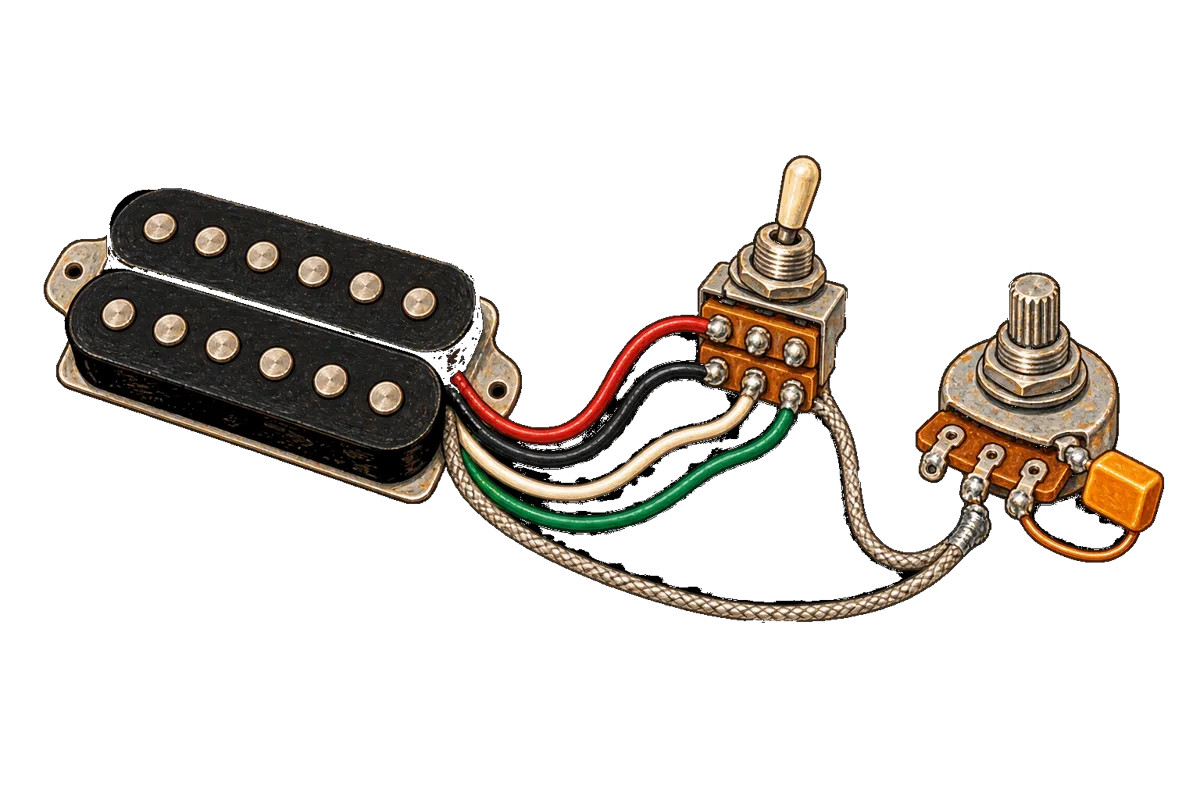
DiMarzio wires the Dual Sound DP101 to a three-position on-on-on DPDT mini toggle so that up is parallel, centre is split and down is series. All five pickup leads go to the switch or to ground, and the switch lug that holds the red lead also carries the signal to the volume. The volume and tone are wired as in any one-humbucker guitar.
This article walks through DiMarzio’s one-humbucker, one-volume, one-tone Dual Sound sheet as drawn in our library, lug by lug.
The pickup
DiMarzio describes the Dual Sound as “the original 4-conductor version of the Super Distortion”, and says that “originally, the main purpose of 4-conductor wiring was to switch from series to parallel modes”. The same page says it is now popular in the bridge of H-S-H guitars, where it can split to single coil. DiMarzio lists 1974 as the year it was introduced and recommends it mainly for the bridge of solid-body guitars.
Four conductors mean each coil has both of its ends on a lead you can reach. DiMarzio’s standard 4-conductor instructions give the colour code: red is the hot output, green and bare go to ground, and black and white are soldered together and taped for normal series humbucking. The Dual Sound switch takes the black, white and red leads and changes what they connect to. The green lead goes to the switch too, but that lug is wired straight to ground.
The diagram
One humbucker, volume, tone, EP1108 on-on-on dual sound, drawn by Tinkercaster from DiMarzio's 1 Humbucker, 1 Volume, 1 Tone, Dual Sound Split sheet (PDF).
Parts, connections and bench checks ↗Open interactive diagram ↗Parts, with the compatible examples the diagram names. The switch is labelled “DPDT on-on-on dual sound” in the drawing.
| Part | Compatible example |
|---|---|
| Bridge humbucker | DiMarzio Dual Sound DP101 |
| On-on-on DPDT switch | DPDT Mini-Toggle (on-on-on), the six-lug EP1108 type |
| Volume, 500k | CTS 500k Audio Pot |
| Tone, 500k | CTS 500k Audio Pot |
| Tone capacitor, .022 µF | Orange Drop .022µF |
| Output jack | Switchcraft #11 |
| Bridge ground | Bridge ground wire |
Lug by lug
The diagram numbers the switch lugs T1 to T6, using our catalog’s layout for a six-lug mini toggle, where T2 and T5 are the two commons. The drawing notes that DiMarzio’s sheet shows the EP1108 with six lugs.
| From | To | Lead |
|---|---|---|
| Pickup green | Switch T1 | green |
| Switch T1 | Volume casing | black |
| Pickup bare | Volume casing | bare |
| Pickup red | Switch T4 | red |
| Pickup white | Switch T5 (common) | white |
| Pickup black | Switch T6 | black |
| Switch T6 | Switch T2 (common) | black jumper |
| Switch T4 | Volume lug 3 (input) | signal |
| Volume lug 2 (wiper) | Output jack tip | signal |
| Volume lug 1 | Volume casing | ground |
| Volume lug 3 | Tone middle lug | signal |
| Tone bottom lug | .022 µF capacitor | yellow |
| .022 µF capacitor | Tone casing | ground |
| Volume casing | Tone casing | ground |
| Tone casing | Output jack sleeve | ground |
| Bridge ground | Output jack sleeve | ground |
Two details are easy to miss. The black lead appears on two lugs: it is soldered to T6, and a jumper takes it on to the common T2. And T4 is a junction: the pickup’s red lead and the wire to the volume input share that lug, so red always reaches the volume whatever the switch does.
What each position does
The switch only changes where the white and black leads go. Red stays on the volume input and green stays on ground. The diagram gives these results:
| Toggle | Mode | Result in the diagram |
|---|---|---|
| Up | Parallel | Bridge humbucker (coils in parallel) |
| Centre | Split | Bridge humbucker (split to one coil) |
| Down | Series | Bridge humbucker (both coils) |
Following the drawing through the switch:
- Down, series. The common T5 joins white to black on T6, and the common T2 goes to the unused T3. Black and white are joined to each other and to nothing else, which is the taped series link of DiMarzio’s standard 4-conductor hookup.
- Up, parallel. T5 joins white to red on T4, so white goes to the hot output. T2 joins black to T1, which is ground with green. Each coil now sits directly between hot and ground.
- Centre, split. In the centre, our catalog’s model of this switch has the common T2 bridging T1 and T3, and leaves the common T5 connected to nothing. T2 takes black to ground on T1, and white on T5 is left open. The coil from red to black is the only one between hot and ground. The other coil has green on ground and white open, so no signal passes through it.
On whether each mode cancels hum, DiMarzio’s Tone Zone T page describes 4-conductor wiring giving “parallel humbucking and split-coil modes”. So of the three positions, only the split gives up humbucking. Series vs parallel wiring explains why parallel still cancels hum. Coil split wiring diagram explains why a split does not.
Same switch, upside down: Seymour Duncan’s version
Seymour Duncan draws the same three modes on the same type of on-on-on toggle, but in the opposite order.
One humbucker, volume, mini-toggle series/split/parallel, drawn by Tinkercaster from a Seymour Duncan sheet.
Parts, connections and bench checks ↗Open interactive diagram ↗| Toggle | DiMarzio | Seymour Duncan |
|---|---|---|
| Up | Parallel | Series |
| Centre | Split | Split |
| Down | Series | Parallel |
The Seymour Duncan drawing uses that maker’s colour code, with black as the hot lead to the volume and the white lead on one common, and it has no tone control. Its compatible example pickup is the SH-4 JB. Do not mix the two sheets: use the drawing from the maker of the pickup you are installing, because the lead colours differ between makers (see Gibson vs Fender pickup wire colour codes for how codes vary). Whichever sheet you follow, confirm each toggle position against its table before you close the guitar.
Before you solder
- Identify the lugs on the switch in your hand. Our catalog’s T1 to T6 layout is a reference, not a promise about every brand. With a meter on continuity, find the two commons and check which outer lug each one reaches in each toggle position.
- Black goes on T6 and also jumps to T2, and T4 takes both the red lead and the wire to the volume. Check both ends of the jumper and both wires on T4 before you plug in.
For setting up the meter, see the multimeter course.
Next step
Open the DiMarzio Dual Sound diagram and keep it beside the bench while you wire. Other DiMarzio layouts are in the DiMarzio section of the library.
References
From the Tinkercaster library
- One humbucker, volume, tone, EP1108 on-on-on dual sound (DiMarzio): connections and switch positions
- One humbucker, volume, mini-toggle series/split/parallel (Seymour Duncan): the reversed switch order
- Catalog: DiMarzio Dual Sound DP101, DPDT Mini-Toggle (on-on-on), CTS 500k Audio Pot, Orange Drop .022µF, Switchcraft #11, Seymour Duncan SH-4 JB
Manufacturer sources
- DiMarzio, 1 Humbucker Wiring: 1 Volume, 1 Tone, Dual Sound Split: “Up Position = Parallel; Center Position = Split”, series down, DPDT on-on-on switch
- DiMarzio, the same sheet as a PDF
- DiMarzio, Dual Sound DP101: original 4-conductor Super Distortion, series/parallel purpose, splitting in H-S-H bridges, introduced 1974
- DiMarzio, How do I connect a 4-conductor pickup?: red hot, green and bare to ground, black and white joined for series
- DiMarzio, Tone Zone T: 4-conductor wiring gives parallel humbucking and split-coil modes