 Tinkercaster
Wiring ideas
Series vs parallel wiring explained
What series and parallel do to two coils or two pickups: output, DC resistance, brightness and hum cancelling, with switching tables and meter readings from Seymour Duncan and Tonerider diagrams.
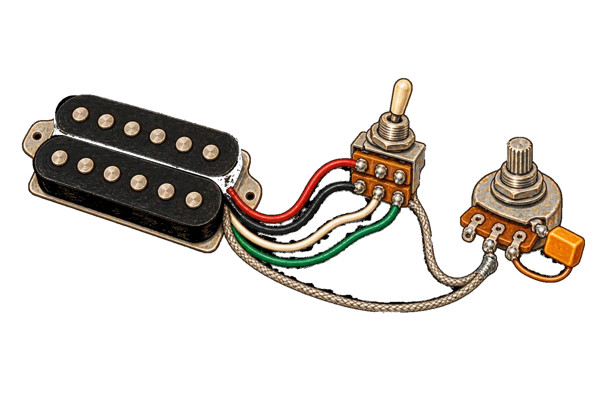
In series, two coils are joined end to end. The signal passes through one and then the other, so their outputs add, and so do their resistance and inductance. The result is louder and fuller, with less top end. In parallel, both coils connect across the same two points, hot and ground. Output drops to roughly that of one coil, total resistance falls below either coil’s, and the sound is brighter and cleaner. With a humbucker, parallel still cancels hum. Only a coil split gives that up.
The same two arrangements apply whether you are joining the two coils inside one humbucker or two separate pickups. Every standard pickup selector already uses parallel: the in-between positions on a Strat, Tele or Les Paul put two pickups in parallel. Series between pickups needs extra switching, such as a Tele four-way or a push/pull. This article explains the electrical difference and then works through three diagrams from our library, with their switching tables and the meter readings that prove each state.
What changes electrically
Think of each coil as a voltage source (the string signal) with a series resistance and inductance.
| Property | Two coils in series | Two coils in parallel |
|---|---|---|
| Signal voltage | The two coils’ voltages add | About that of one coil, when the coils are matched |
| DC resistance | Sum of both coils | Less than either coil alone |
| Inductance | Adds, so the resonant peak sits lower | Lower, so the resonant peak moves up |
| Sound | Fuller, more output | Brighter, cleaner, less output |
| Hum cancelling (humbucker) | Yes | Yes |
Seymour Duncan’s article on the advantages and disadvantages of series vs parallel puts the resistance side plainly: in series “you have maximum DC resistance of both coils added together”, and in parallel “the total DC resistance is less than either coil individually”. It describes series as giving “maximum fullness and output”. DiMarzio’s 4-conductor pickup instructions describe the parallel humbucker as “slightly less powerful, with more highs and an overall cleaner sound”.
The numbers follow from Ohm’s law. Take two matched coils of resistance r. In series they read 2r. In parallel they read r/2, a quarter of the series figure. The bench checks in the diagrams below use that relationship.
DC resistance tells you which way the coils are connected and says nothing about tone. The brightness change comes from the lower inductance moving the pickup’s resonant peak up, and the resistance reading only confirms that the switch has done what the drawing says.
Why parallel still cancels hum
A humbucker’s two coils have opposite magnetic polarity and are connected in opposite directions. Seymour Duncan’s humbucker internals article explains the result: reversing the wiring direction through one coil, combined with the opposite magnet, keeps “the string signal in phase across both coils”. Hum is induced by external fields, “which aren’t affected by the pickup’s magnetic polarity”, so it arrives out of phase and cancels.
Nothing in that argument depends on the coils being in series. In parallel, the coils are connected so that their string signals add at the hot node while their hum voltages oppose. With matched coils the hum cancels there too. DiMarzio says so directly: in parallel “the pickup will still cancel hum”, and “Dual Sound wiring cancels hum in both positions”. DiMarzio also separates parallel from a split: “Parallel wiring is not the same as turning off one coil. Turning off a coil means the pickup is no longer humbucking.”
| Mode | Coils in use | Output | Hum cancelling |
|---|---|---|---|
| Series | Both, end to end | Highest | Yes |
| Parallel | Both, side by side | Lower | Yes |
| Split | One | Lowest | No |
DiMarzio’s own product pages use the same distinction. The Tone Zone T lists “4-conductor wiring” that “provides parallel humbucking and split-coil modes”.
How the leads connect in each mode
To wire a humbucker for parallel you need all four coil leads, which means a 4-conductor lead. The link joint that series normally tapes off at the pickup has to reach the switch. Using Seymour Duncan colours (black, white, red, green) and DiMarzio colours (red, black, white, green):
| Mode | Seymour Duncan colours | DiMarzio colours | Source |
|---|---|---|---|
| Series | Red + white joined and insulated; black hot; green + bare ground | Black + white joined and insulated; red hot; green + bare ground | Seymour Duncan sheet 2H_3G_1V_1T; DiMarzio 4-conductor instructions |
| Parallel | Black + red hot; white + green ground | Red + white hot; green + black ground | Our Seymour Duncan Music Man diagram (below); DiMarzio 4-conductor instructions |
| Split | Red + white joined to ground | Depends on which coil is kept; see the sheet | Seymour Duncan humbucker internals |
Fralin’s series/parallel mod gives its own colours. It uses a 500K push/pull where, pushed, red connects to green (series), and, pulled, red connects to white and green to black (parallel). Fralin’s code is not Seymour Duncan’s or DiMarzio’s, and Fralin notes that “other manufacturers have different color codes”. Wire from your pickup’s own sheet. Our Gibson vs Fender pickup wire colour codes article compares them.
Walkthrough: one humbucker on a push/pull
One humbucker with a push/pull series/parallel volume, drawn by Tinkercaster from Seymour Duncan sheet 1H_1VppSP.
Parts, connections and bench checks ↗Open interactive diagram ↗One humbucker with a push/pull series/parallel volume is the smallest complete circuit in our library that switches a humbucker between series and parallel. Parts: a four-conductor humbucker in Seymour Duncan colours, a Volume 500k push/pull (catalog example: CTS 500k Push-Pull DPDT), an output jack (Switchcraft #11) and a bridge ground wire.
The DPDT on the pot has two columns of three lugs, and each column is one pole. The drawing’s connections:
- Pickup white goes to the left middle lug, and pickup red to the right middle lug. These are the two poles’ commons, and they are why red and white are not taped together here.
- A short jumper joins the left middle lug to the right top lug. The left top lug stays empty.
- Green and bare share the left bottom lug, which is wired to the volume casing (ground).
- Pickup black shares the right bottom lug, which is wired to the volume’s input lug. The volume middle lug goes to the jack tip, and the right lug is bent onto the casing.
Pulling the knob moves each common to the lug nearest the pot. The drawing states that as an assumption, because the sheet does not say which knob position is series.
| Knob | Left pole (white) | Right pole (red) | Result |
|---|---|---|---|
| Pushed down | Left middle to left top (empty); the jumper carries white to the right top | Red to right top, where it meets white | Red joined to white: series. Black hot, green ground |
| Pulled up | White to left bottom: ground, with green | Red to right bottom: hot, with black | Parallel |
The bench checks, with the meter across the jack and the volume full up:
- Knob down: tip to sleeve reads the full humbucker’s resistance.
- Knob up: the reading drops to roughly a quarter of the series reading.
- Volume at zero: tip and sleeve read as a short in both knob positions.
The quarter is the matched-coil arithmetic above. If the reading barely changes when you pull the knob, the switch is not moving the link, so check the jumper and the two middle lugs first. If pulling the knob gives a reading close to half the series figure instead of a quarter, one coil has been shorted rather than paralleled, which means you have wired a split by mistake.
Three sounds from a three-way blade
Esquire with one humbucker, series, parallel and split on a three-way blade, drawn by Tinkercaster from Seymour Duncan sheet Esq_1H_SSP.
Parts, connections and bench checks ↗Open interactive diagram ↗Seymour Duncan’s Esquire series/parallel/split sheet uses a Tele-style blade (catalog example: CRL 3-Way Blade) as a two-pole, three-position switch, with a 250k volume, a 250k tone and a .047 µF capacitor. Red goes to the left column’s bottom lug and white to the right column’s top lug, and each is its pole’s common. Black goes straight to the volume’s left lug and green and bare to the volume casing, so they never pass through the switch. Only the link leads are switched, and that is enough to give all three modes:
| Position | Sheet legend | What the link leads do |
|---|---|---|
| 1 | Humbucker in series | Red and white are joined to each other, away from ground |
| 2 | Humbucker in parallel | Red joins black (hot) and white joins green (ground) |
| 3 | Humbucker split to the slug coil | Red and white both go to ground |
Its bench checks are made on the leads themselves:
- Position 3: red and white each read as a short to ground.
- Position 1: red and white read joined to each other and open to ground.
Those two checks are how you tell series from split on the bench. In series the link must be insulated from everything. If it touches ground, the coil beyond it is shorted out and you have an accidental coil split, which is thinner and no longer hum-cancelling. For the full treatment of splits, see our coil split wiring diagram article.
The same pattern appears on Seymour Duncan’s Music Man three-way sheet. That sheet is for a Music Man bass humbucker feeding an active preamp that is not drawn. Its hand-traced states are: position 1 parallel (red joins black at the preamp input, white joins green at ground), position 2 split, and position 3 series, with white and red joined and taken to ground through a 3.3k resistor. The resistor makes that position a variant of the plain series link.
Two pickups: parallel is the default, series is the mod
A standard selector’s in-between positions put two pickups in parallel. Seymour Duncan makes the point about a Strat’s positions 2 and 4, which “are often mistakenly called the ‘out of phase’ position. The pickups are connected in parallel and are properly in phase.” Of the 330 diagrams in our library, 279 have at least one switch position that puts pickups or coils in parallel. Only 39 have a position that puts them in series.
Tonerider four-way Telecaster, drawn by Tinkercaster from sheet WD_SS_11L4.
Parts, connections and bench checks ↗Open interactive diagram ↗The best-known series mod is the Tele four-way. Tonerider’s four-way Telecaster uses a four-way blade (catalog example: Oak Grigsby 4-Way Tele Mod Switch), a 250k volume, a 250k tone and a .022 µF capacitor:
| Position | Sheet legend | Bench check |
|---|---|---|
| 1 | Bridge | Continuity from tip to sleeve through the bridge pickup only |
| 2 | Neck + Bridge (Parallel) | Lower than either pickup alone |
| 3 | Neck | Continuity through the neck pickup only |
| 4 | Neck + Bridge (Series) | Higher than either pickup alone |
Position 4 explains the one unusual instruction on the sheet. In a stock Tele, the neck pickup’s black lead is ground and the metal cover is tied to it. In this harness the neck black goes to the switch common instead. The switch grounds it in the neck and parallel positions and uses it as the link between the pickups in series. In position 4 that lead carries signal, so a cover tied to it would carry signal too. The sheet therefore says to “disconnect the cover of the neck pickup and run a separate ground for it”. Seymour Duncan’s alternate Tele wiring article gives the same instruction and describes position 4 as “a big boost in output and a big, fat tone”. Our Telecaster 4-way switch article covers the full build. Our library holds nine four-way Tele diagrams.
Two humbuckers can be put in series with a push/pull. On Seymour Duncan’s two humbuckers, toggle, series/parallel and phase push/pulls (sheet 2H_3G_1V_2TppSPppPH), the neck tone’s push/pull either grounds the neck green and sends the bridge signal to the toggle (parallel) or joins the bridge signal to the neck green (series). In series, the neck pickup’s ground end is lifted and fed by the bridge pickup. That is why the drawing’s bench checks read “toggle positions 1 and 2 read both humbuckers in series; position 3 reads open”: the bridge signal has been moved off the toggle’s bridge lug. Seymour Duncan’s own 2H_3G_2VppSP_2T sheet takes the other approach, with a series/parallel push/pull on each volume switching each humbucker’s own coils.
Whether two separate pickups cancel hum in series or parallel depends on their relative magnetic polarity and winding direction, exactly as with a humbucker’s two coils. The Tonerider drawing records that its source does not state the magnet polarity, so check your pickups’ specifications before you rely on a quiet position 4.
Where to find these circuits in our library
- 25 diagrams name series/parallel switching in the title or specification, 23 from Seymour Duncan and 2 from DiMarzio. They include one-humbucker push/pulls, two-humbucker blade and toggle harnesses, and Triple Shot ring combinations.
- Gibson’s pickup wiring sheet draws series/parallel on a DPDT on/on mini-toggle for its four-conductor models (490R/490T, 498T, 496R, 500T, Tony Iommi), labelling the positions “Series ‘Humbucking’ Sound” and “Parallel ‘Single Coil’ Sound”.
- For a three-position mini-toggle, DiMarzio states that an on-on-on DPDT (EP1108) gives series and parallel on the outer positions and single coil in the centre. Our catalog lists a DPDT Mini-Toggle (on-on-on).
Reading the meter: a summary
Measure across the jack with the volume full up, the guitar unplugged and any battery removed.
| State | Expected reading | What a wrong reading means |
|---|---|---|
| Humbucker in series | Sum of both coils | Much lower: link grounded (accidental split) or a coil shorted |
| Humbucker in parallel | About a quarter of the series reading, for matched coils | About half: one coil shorted, which is a split |
| Humbucker split | About half the series reading, for matched coils | Unchanged from series: the link is not reaching ground |
| Two pickups in parallel | Lower than either pickup alone | Equal to one pickup: the other is not connected |
| Two pickups in series | Higher than either pickup alone | Open: the lifted ground end is not being fed |
These readings verify the topology but cannot tell you whether two coils are in phase. Out-of-phase coils read the same resistance but sound thin, so after the meter check, finish with a listening check at low volume.
Before you solder
Series/parallel switching puts several leads on small DPDT lugs close together. Tin the leads, keep the insulated link lead clear of the pot casing, and inspect each lug for bridges before you close up. Never solder with the guitar plugged into an amp. Use fume extraction and wash your hands after handling leaded solder. Our soldering guide covers the technique, and the controls and switching course covers push/pull, coil split, series/parallel and phase in depth. If a pickup goes silent after the mod, work through how to fix a dead pickup.
Next step
Open one humbucker with a push/pull series/parallel volume and follow each knob state against its table. Then read the Seymour Duncan series, split and parallel guide. The library and guides are free to browse, and you can open that diagram on your own board for free, add a second pickup and a four-way or push/pull, and let the wiring checks confirm each position before you solder. Tinkercaster Pro adds Luthier, the AI assistant (with a usage limit), and guided builds. For the pot values these harnesses use, see 250k vs 500k pots.
References
From the Tinkercaster library
- One humbucker with a push/pull series/parallel volume (Seymour Duncan 1H_1VppSP): lug-by-lug push/pull wiring, series and parallel states, quarter-reading bench check.
- Esquire with one humbucker, three-way blade series/parallel/split (Seymour Duncan Esq_1H_SSP): three modes on a blade, link-lead checks.
- Music Man pickup, 3-way blade parallel/split/series (Seymour Duncan WD_MM_3B): parallel lead pairing in Seymour Duncan colours.
- Four-way Telecaster wiring (Tonerider WD_SS_11L4): parallel and series positions, separate neck cover ground.
- Two humbuckers, toggle, series/parallel and phase push/pulls (Seymour Duncan 2H_3G_1V_2TppSPppPH): pickup-to-pickup series with a push/pull.
- Guide: Seymour Duncan series, split and parallel wiring. Course: Controls & switching.
- Catalog: CTS 500k Push-Pull DPDT, CRL 3-Way Blade, Oak Grigsby 4-Way Tele Mod Switch, DPDT Mini-Toggle (on-on-on), Switchcraft #11.
Manufacturer and technical sources
- Seymour Duncan: advantages and disadvantages of series vs parallel: DC resistance in series and parallel, fullness and output, Strat positions 2 and 4 as parallel and in phase.
- Seymour Duncan: humbucker internals explored: why reversed wiring and opposite magnets cancel hum, splitting by grounding the link.
- DiMarzio: 4-Conductor Pickup Instructions: series and parallel colour connections, parallel still cancels hum, split does not, EP1108 series/single/parallel.
- DiMarzio: The Tone Zone T: parallel humbucking and split-coil modes from 4-conductor wiring.
- Fralin: Series / Parallel humbucker wiring mod: 500K push/pull series/parallel, Fralin colour connections, 4-conductor lead required.
- Seymour Duncan sheet 2H_3G_1V_1T: standard series connection in Seymour Duncan colours.
- Seymour Duncan sheet 2H_3G_2VppSP_2T: series/parallel push/pull on each volume for two humbuckers.
- Seymour Duncan: three cool alternate wiring schemes for Telecaster: four-way series position and the separate neck cover ground.
- Gibson pickup wiring diagrams (PDF): series/parallel DPDT mini-toggle wiring for Gibson four-conductor models.