 Tinkercaster
Wiring ideas
How to wire a Telecaster (4-way switch)
A connection-by-connection walk through Tonerider's four-way Tele harness: why the neck ground is switched, why the cover needs its own wire, and what to meter in each position.
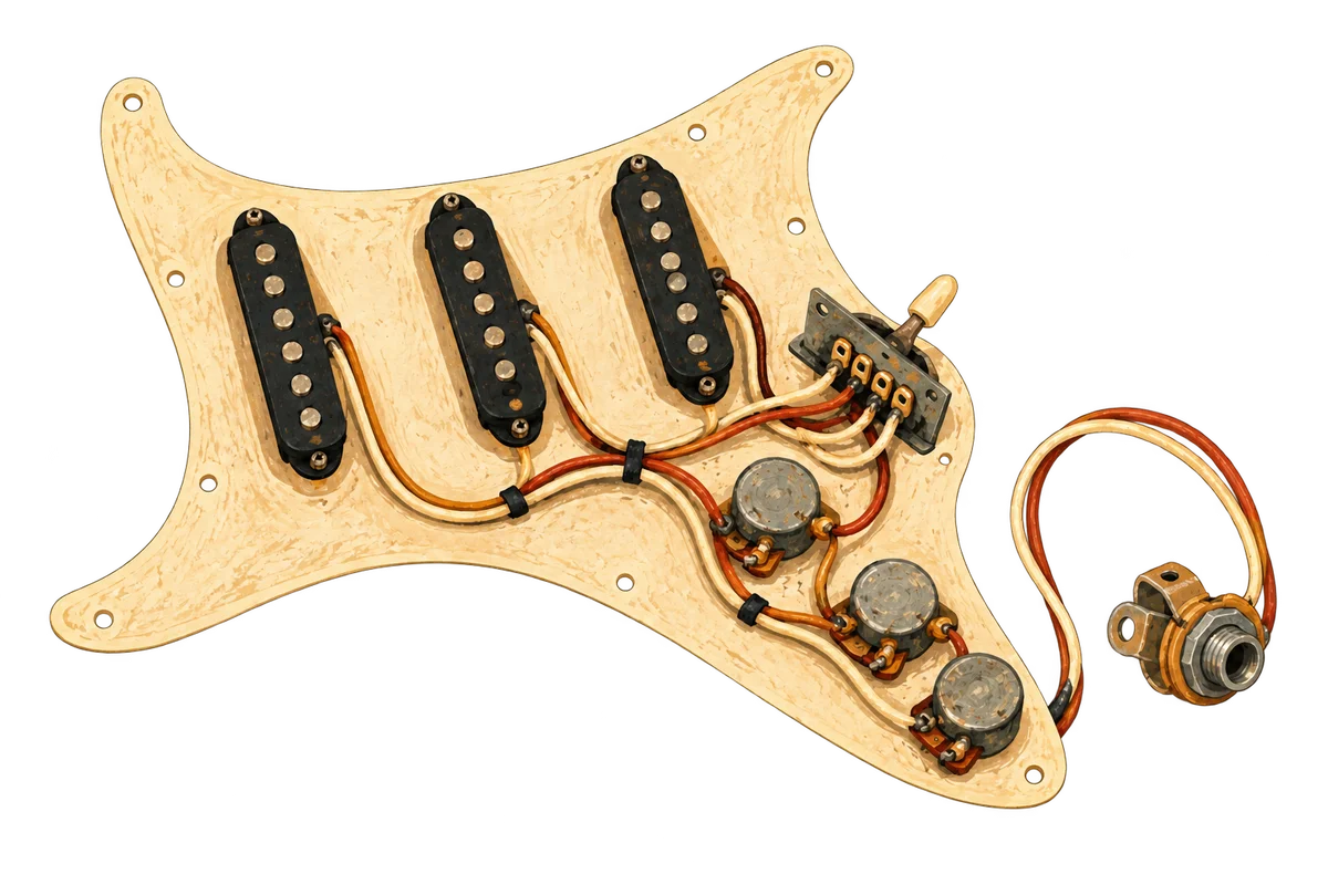
A four-way Telecaster harness keeps the three stock sounds and adds a fourth: both pickups in series. On a two-pole, four-position Tele blade such as the Oak Grigsby 4-Way Tele Mod Switch, the positions run bridge, neck and bridge in parallel, neck, then neck and bridge in series. StewMac’s instructions for that switch give the same order. The one change outside the control plate is the neck pickup: its cover must come off the black lead and go to ground on a wire of its own, because the black lead stops being a ground.
This article walks through one harness in full, our drawing of Tonerider’s four-way Telecaster sheet, and then compares it with the other four-way Tele sheets in our library from Seymour Duncan and DiMarzio.
The parts in the Tonerider harness
Our drawing of Tonerider sheet WD_SS_11L4 uses these parts. Where the sheet names only a value, the diagram marks the catalog part as a compatible example; Tonerider does not specify it.
| Part | Value or type on the sheet | Compatible example in our catalog |
|---|---|---|
| Neck pickup | Two-conductor single coil, yellow hot, black, plus a green cover ground | Generic single coil |
| Bridge pickup | Two-conductor single coil, white hot, black | Generic single coil |
| Switch | Four-way blade | Oak Grigsby 4-Way Tele Mod Switch |
| Volume | 250k | CTS 250k Audio Pot |
| Tone | 250k | CTS 250k Audio Pot |
| Tone capacitor | .022 µF | Orange Drop .022µF |
| Output jack | Mono | Switchcraft #11 |
Our catalog lists the Oak Grigsby part as a blade with four positions, two poles and ten tags. The source sheet does not number the switch lugs, so our drawing names them by column and row: L1 to L5 down the left, R1 to R5 down the right, with the two commons at opposite ends (R1 and L5). Other drawings number the same switch T1 to T10. Lug names are only a labelling convention, so use the meter to find which tag is which on the switch in your hand.
Tonerider four-way Telecaster, drawn by Tinkercaster from sheet WD_SS_11L4.
Parts, connections and bench checks ↗Open interactive diagram ↗Every connection, and why it is there
Here is the diagram’s connection list grouped by job. The numbers match the list on the diagram page.
Pickup leads to the switch
- (10) Bridge white to switch R1, the right-hand common.
- (11) Neck yellow to switch R2.
- (1) Neck black to switch L5, the left-hand common.
That last connection is what makes the circuit work. A stock three-way Tele takes the neck black straight to ground; this harness sends it to a switch common, so the switch decides what the bottom of the neck coil connects to: ground, nothing, or the bridge pickup.
Jumpers on the switch
- (12) R2 to R3.
- (15) L2 to L3.
- (14) L4 to R5, the one jumper that crosses between the two poles.
Switch to controls
- (13) R3 to the volume’s left lug, the input.
- (2) L3 to the volume casing, which is ground.
Volume, tone and jack
- (16) Volume middle lug (wiper) to jack tip.
- (4) Volume right lug bent onto the volume casing.
- (17) Volume left lug to tone left lug.
- (5, 6) Tone middle lug to the .022 µF capacitor, and the capacitor’s other leg to the tone casing.
- (7, 8) Volume casing to tone casing, tone casing to jack sleeve.
Grounds
- (3) Bridge black to the volume casing. The bridge pickup’s ground never moves.
- (9) The ground wire from the bridge plate to the volume casing.
- (18) The neck cover’s separate green wire to the volume casing. The diagram lists this connection but does not draw it, because the generic single coil in the drawing has no cover terminal.
The diagram notes that L3, the bridge black, the neck cover ground and the bridge ground wire all end on one solder spot on the volume casing.
How the switch produces four sounds
The sheet prints the positions. Tracing the connection list shows how each one is made. On each pole the common reaches one contact per position, stepping down the bank: R1 reaches R2, R3, R4 and R5 in turn, and L5 reaches L1, L2, L3 and L4. That stepping is the reading that fits all four printed positions. Confirm it on your switch before you solder, because the physical order can differ between switch makes.
| Position (sheet) | Bridge white (R1) reaches | Neck black (L5) reaches | Result |
|---|---|---|---|
| 1. Bridge | R2, jumpered to R3 and the volume | L1, not connected | Bridge only. The neck hot sits on the output but its black is open, so no current flows through it. |
| 2. Neck + Bridge (Parallel) | R3, the volume | L2, jumpered to L3 and ground | Both pickups from output to ground, side by side. |
| 3. Neck | R4, not connected | L3, ground | Neck only. |
| 4. Neck + Bridge (Series) | R5, jumpered to L4 | L4 | Neck yellow at the output, through the neck coil, neck black to bridge white, through the bridge coil, bridge black to ground. |
The neck yellow is on the volume input in every position, so the switch turns the neck on and off by connecting or lifting its ground end while the hot end stays put. In position 4 the neck black is the junction between the two coils and carries signal, which is why it must be insulated from everything along its run to L5.
Series sends the signal through both coils in a chain, while parallel connects both across the same output and return, as our series, split and parallel guide sets out for humbucker coils. The same distinction applies to two separate pickups: in series their DC resistances add. Seymour Duncan’s alternate Tele wiring article describes the result as “a big boost in output and a big, fat tone”. Whether the parallel and series positions cancel hum depends on the magnet polarity and winding direction of your two pickups. The Tonerider sheet does not state it, so our diagram does not claim it.
Why the neck cover needs its own ground
A stock Tele neck pickup has its metal cover tied to the black lead by a short bare jumper. In a three-way harness that grounds the cover. In this harness the black lead is not always at ground:
- In position 4 the neck black is the series junction, so a cover tied to it sits at signal level.
- In position 1 the neck black is open, so the cover floats.
Either way the cover stops shielding the coil. Lollar’s four-way Tele diagram prints the consequence: running the pickups in series without the separate cover ground wire “will cause excessive noise”. Seymour Duncan’s article gives the procedure: flip the pickup, cut the uninsulated jumper to the cover, leave a short nub on the cover, and solder a new wire from that nub to ground. StewMac says the same for the Oak Grigsby switch: disconnect the cover from the black lead and run it to ground with a separate lead.
Doing only half the job produces a recognisable fault. If you add the cover wire but leave the jumper in place, the neck black is grounded permanently. Position 1 then behaves like position 2 (both pickups in parallel), and position 4 gives the neck alone, because the bridge pickup has ground at both ends. The same symptom appears if the neck black’s insulation is damaged against a grounded surface.
The bridge pickup needs none of this. Its black goes to ground in every position (connection 3), so its baseplate or cover ground can stay as it is.
Check it before plugging in
Our diagram lists these bench checks. The sheet gives no pickup resistances, so there are no fixed numbers. Measure each pickup on its own first and write down its DC resistance. Call them Rn (neck) and Rb (bridge). Set the meter to resistance, volume on full, and probe the jack tip and sleeve (the tone path has a capacitor in it, so it reads open at DC).
| Position | Expected reading at the jack | If it reads wrong |
|---|---|---|
| 1. Bridge | Rb | Reads the parallel value: neck black is grounded (see above). |
| 2. Parallel | Lower than either pickup: Rn × Rb / (Rn + Rb) | Reads Rb: neck black not reaching L2/L3 ground. |
| 3. Neck | Rn | Open: L3 not grounded, or neck black not on L5. |
| 4. Series | Higher than either pickup: close to Rn + Rb | Reads Rn: bridge shorted out, neck black grounded. Reads open: the L4 to R5 jumper is missing. |
| Any, volume at zero | A short | Volume wiper or casing ground fault. |
The 250k volume track sits across the pickup at DC, so every reading comes out slightly lower than the pickup alone. The multimeter course covers the meter technique, including why a reading can look right when a joint is poor.
How the other four-way Tele sheets compare
Our library has 9 four-way Tele diagrams: this Tonerider sheet, seven from Seymour Duncan, and DiMarzio’s Richie Kotzen harness. All 9 use 250k pots. Where they differ is the tone capacitor and, in one case, the whole switch layout.
Seymour Duncan two single coils, four-way, one volume and one tone, drawn by Tinkercaster from sheet Tele_2S_4B_1V_1T.
Parts, connections and bench checks ↗Open interactive diagram ↗Seymour Duncan, two single coils. Our drawing of Seymour Duncan’s four-way sheet has the same switch connections as the Tonerider one, lug for lug: bridge white to R1, neck white to R2, neck black to L5, the R2 to R3, L2 to L3 and L4 to R5 jumpers, R3 to the volume input and L3 to ground. The differences are the lead colours (the neck hot is white, not yellow) and the capacitor: .047 µF instead of .022 µF. All seven Seymour Duncan four-way sheets in our library use .047 µF. Both Tonerider and DiMarzio use .022 µF. Seymour Duncan’s pots and caps guide describes .047 µF as darker than .022 µF and suited to bright guitars such as Telecasters. Lollar’s sheet gives .047 as the standard Fender value and says anything from .047 to .015 can be used. The choice comes down to taste, since both values fit the same two lugs (Orange Drop .047µF in our catalog).
Seymour Duncan, other pickup pairs. The same sheet family covers a humbucker bridge with a single-coil neck, two Tele stacks and other combinations. All seven keep the bridge, parallel, neck, series order.
DiMarzio Richie Kotzen four-way Telecaster, drawn by Tinkercaster from DiMarzio's Richie Kotzen Telecaster 4-Way Wiring sheet.
Parts, connections and bench checks ↗Open interactive diagram ↗DiMarzio, Richie Kotzen. DiMarzio’s sheet pairs a Twang King neck (DP172) with a Chopper T bridge (DP384), a four-conductor rail humbucker, on DiMarzio’s Four-Way Switch with 250K custom-taper pots (EP1200) and a .022 µF capacitor (EP1022). Our drawing shows a different layout inside:
- The neck’s hot (white) lead goes to the volume casing and its black lead goes to switch T1. The Tonerider layout does the reverse: the hot goes to the switch path and only the black is switched.
- The humbucker’s black and white leads are joined and taped off. Its red lead goes to T10 and its green lead to T5, and T5 feeds the volume input.
- The Twang King’s grey cover lead is a separate ground, like the Tonerider green wire.
- The sheet’s legend lists the sounds as bridge, bridge and neck parallel, bridge and neck series, neck. Our drawing follows that order, which puts series before neck. DiMarzio’s product page for the switch describes series as the added fourth position.
The two orders cannot both describe the same switch lugs. Follow one sheet completely with the pickups it names, confirm the position order with the meter table above, and do not take the switch wiring from one maker and the pickup connections from another. The DiMarzio sheet reverses the roles of the leads, so mixing layouts can leave you with a position that is silent or out of phase. See the Seymour Duncan guide to single-coil and Tele phase reversal for what that sounds like.
Across the library, 4 of the 9 four-way diagrams carry an explicit note about a separate neck cover ground: Tonerider, Seymour Duncan’s two-single-coil sheet, Seymour Duncan’s Tele stack neck sheet and DiMarzio’s Kotzen sheet. The rest pair the switch with pickups whose sheets do not raise it. If your neck pickup has a metal cover tied to its black lead, the rule applies whatever the sheet says.
Fitting the switch
DiMarzio describes its Oak Grigsby four-way blade as a direct replacement that needs no change to the control plate, and Tonerider’s diagram index lists its four-way sheet for two single coils with one volume and one tone. In practice the job comes down to swapping the switch, adding one jumper that crosses between poles and modifying the neck cover.
Work in this order: map the new switch with the meter and mark R1 and L5 (or your switch’s equivalents), fit the three jumpers, modify the neck pickup, then wire the leads. Heat-shrink the neck black where it passes other lugs. Unplug the guitar from any amp before you pick up the iron, and keep the soldering cheat sheet on the bench. The article on how to solder guitar wiring covers joint technique, and series vs parallel wiring goes further into what position 4 does electrically.
Build it from the diagram
Open the Tonerider four-way Telecaster diagram and read its connection list against your parts. The diagram, the catalog and the courses are free. You can also open the diagram in the workbench for free and save and customise your own board (for example, swapping in the .047 µF capacitor or a humbucker bridge from the Seymour Duncan variant). With Tinkercaster Pro you can ask Luthier about a connection and follow a guided build with meter checkpoints.
References
From the Tinkercaster library
- Four-way Telecaster wiring (Tonerider WD_SS_11L4): parts, connection list, position table and bench checks walked through above.
- Telecaster wiring with a four-way switch (Seymour Duncan Tele_2S_4B_1V_1T): identical switch layout, .047 µF capacitor.
- Richie Kotzen four-way Telecaster wiring (DiMarzio): alternative layout and position order.
- Telecaster humbucker bridge, single neck, four-way and Telecaster two Tele stacks, four-way: other Seymour Duncan four-way sheets.
- Catalog: Oak Grigsby 4-Way Tele Mod Switch, CTS 250k Audio Pot, Orange Drop .022µF, Orange Drop .047µF, Switchcraft #11.
- Guides and courses: series, split and parallel wiring, single-coil and Tele phase reversal, multimeter course, soldering cheat sheet.
Manufacturer and technical sources
- StewMac: Oak Grigsby 4-way 2-pole lever switch instructions: position order, and the neck cover must be disconnected from the black lead and grounded separately.
- Seymour Duncan: three alternate wiring schemes for Telecaster: series in position 4, and the procedure for cutting the cover jumper and adding a ground wire.
- Lollar Guitars: 4-way Telecaster switch wiring diagram (PDF): series without a separate cover ground causes excessive noise; .047 standard Fender cap, .047 to .015 usable; 250k standard for single coils.
- DiMarzio: Richie Kotzen Telecaster 4-Way Wiring (PDF): pickups, EP1200 250K custom-taper pots, .022 µF EP1022 capacitor, position legend.
- DiMarzio: Four-Way Switch for Tele (EP1113): Oak Grigsby blade, direct replacement, series as the added fourth position.
- Seymour Duncan: best guitar pots and caps: .022 µF as a middle ground and .047 µF as darker, suited to Telecasters.
- Tonerider: wiring diagrams: Tonerider’s four-way sheet for two single coils, one volume, one tone.