The wiring reference

Seymour Duncan coil splitting explained

A humbucker has two coils. See how a switch lets you use just one of them.

Start here · What you are looking at

One pickup. Two coils inside.

A pickup sits under your strings. A magnet and coils of fine copper wire turn string movement into an electrical signal for your amp. This type is called a humbucker: its two coils work together to reduce electrical hum.

1 Screws you can adjust
2 Smooth metal posts
A typical humbucker with its cover removed, viewed from the strings.

1 The screw coil

The row with screw heads. There is a coil of fine wire underneath this half of the pickup.

2 The smooth-post coil

The other row has smooth metal posts, called slugs. “Slug coil” simply means the coil around that row.

What is a coil?

Lots of turns of thin copper wire, with an end at each side. Two coils give us four coloured wire ends to connect.

Why do some diagrams say “north” and “south”?

Those names describe magnetic polarity, not the top and bottom of the guitar. On the conventional Seymour Duncan humbucker shown here, north refers to the smooth-post coil and south to the screw coil. Other designs can differ. “Inner” and “outer” depend on which way the pickup is installed.

Background: Seymour Duncan’s anatomy of a humbucker.

See what changes

See which half of the pickup you are using

Full: both coils contribute

Two working halves = humbucker

Red and white are joined, but not grounded. The two coils are connected one after the other—called series wiring.

The two coils work together to reduce hum.

Split: one coil contributes

Dimmed half = bypassed

The switch connects the red/white joint to ground. In this version, that bypasses the screw coil and leaves the smooth-post coil working.

You get a single-coil-type sound, usually with less output. The pickup no longer cancels hum on its own.

This explains what the circuit does. Use the complete wiring diagram for the exact solder connections.

The source shows two alternatives

Choose which row you keep

Keep the smooth-post coil

Black → signal
Green + bare → ground
Red + white → split switch

Keep the screw coil

Red → signal
White + bare → ground
Green + black → split switch

In either complete variant, the split switch grounds the joined pair to select one coil. Leave the pair joined but ungrounded for the full humbucker. Do not mix the connections from the two variants.

When you are ready to wire it

Applies to

Passive four-conductor humbuckers with separately accessible coil leads. This is a modification to a complete guitar circuit.

One pickup, two switching states

In the standard series setting, both coils form the signal path. A split connection bypasses one coil. The source sheet shows two alternatives depending on which coil you want to retain.

The smooth-post row is the slug coil; the row with screw heads is the adjustable coil. “Inner” and “outer” change when you turn the pickup around, so identify the physical row first.

Check the switch before soldering

The source labels pulled up as split and pushed down as full. Confirm the actual contacts of your push/pull with a continuity meter; rotating the component or viewing it from the opposite side can make the drawing misleading.

  1. Choose the coil you want to retain.
  2. Find the middle switch terminal and check which neighbour it connects to in each position.
  3. Follow one complete wiring variant, keeping the bare shield grounded.
  4. Check both settings before closing the control cavity.
Try a complete coil-split circuit

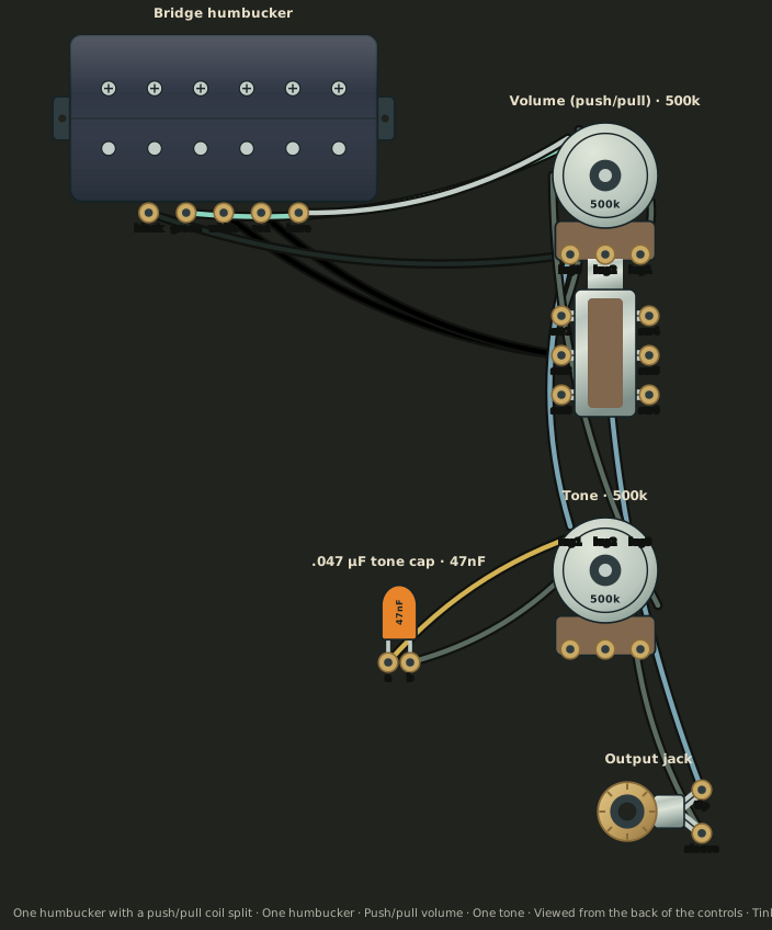
The example below is a reviewed complete wiring diagram. Try its push/pull control in simulation mode and follow the connections. Its electrical checks do not predict the exact sound of your guitar.

Loading interactive diagram…

Viewed from the back of the controls, as you solder them. Select a component to move, rotate or flip it. Follow wires and try the switches in simulation mode. Use Full screen for a closer look.

Source and interpretation

Original explanation by Tinkercaster, based on these Seymour Duncan sheets: WD_Coil_Splitting. The guide describes the stated configuration; it does not establish compatibility with every pickup or switch.

Not affiliated with or endorsed by Seymour Duncan. Refer to your exact component’s instructions when a detail differs.

See it in a complete diagram

Put it in a complete circuit

Use a complete wiring diagram to see how the pickup, controls and output connect. Our public diagrams are free to view and explore.

Browse Seymour Duncan diagrams →