 Tinkercaster
Wiring ideas
How to wire a Jazzmaster (3-way switch)
The stock Jazzmaster runs two circuits: a lead circuit on a 3-way toggle with 1M pots, and a neck-only rhythm circuit on a slide switch. Fender's parts, values and checks.
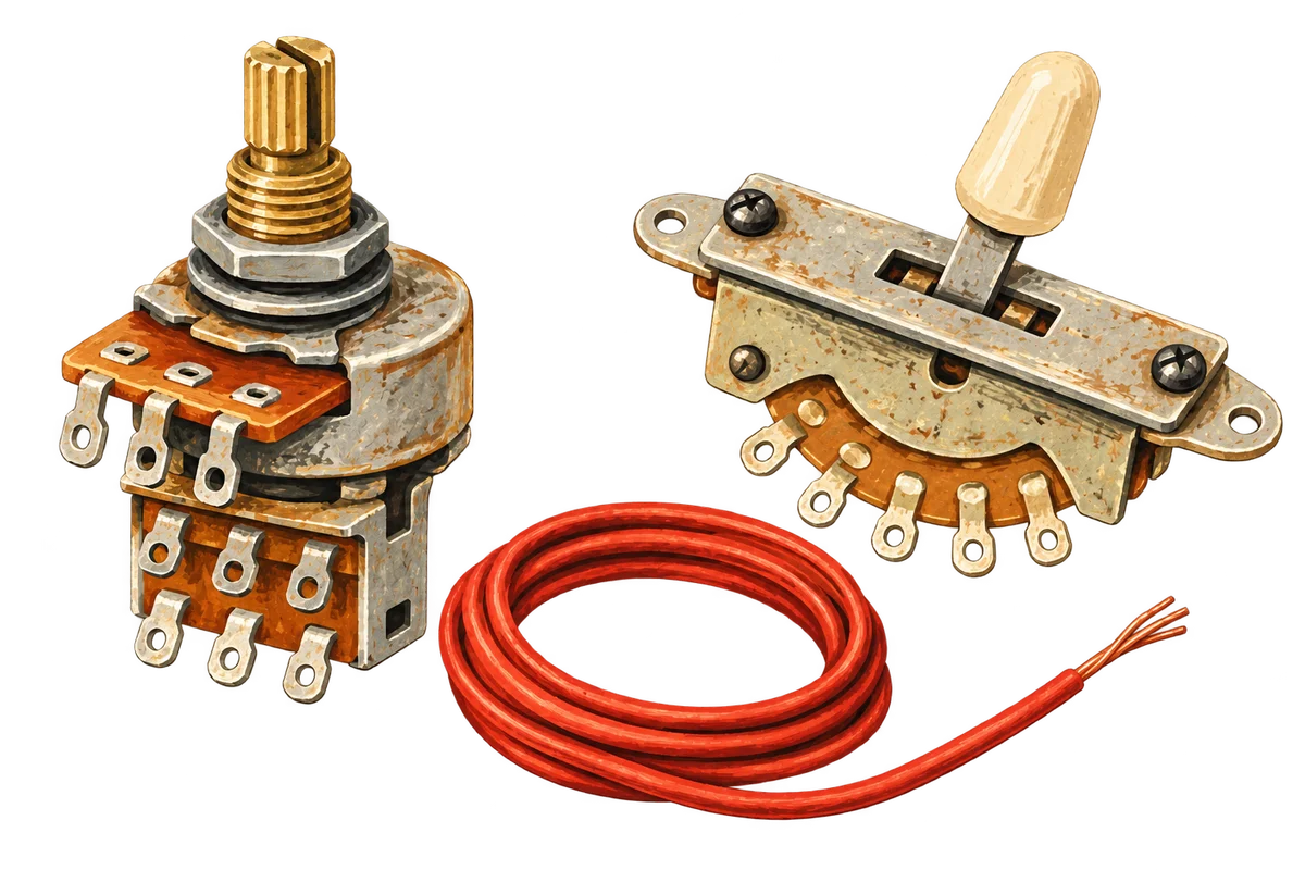
A stock Fender Jazzmaster has two separate circuits, and the 3-way switch belongs to only one of them. The toggle selects the neck pickup, both pickups or the bridge pickup for the lead circuit, which runs through a master volume and master tone on 1M pots. A two-position slide switch on the upper horn chooses between that lead circuit and a rhythm circuit. The rhythm circuit uses the neck pickup only, through its own volume and tone roller wheels: a 1M rhythm volume and a 50k rhythm tone. This article sets out Fender’s parts and values, how the two circuits interact, and how to check a Jazzmaster harness with a meter.
The Tinkercaster library does not have a Jazzmaster diagram. None of our 330 drawings is a Jazzmaster or rhythm circuit, and none of them uses a 1M or 50k pot, so everything below about the Jazzmaster circuit comes from Fender’s own documents. We link the library diagrams further down only for the techniques they share with it.
Fender’s parts list
The clearest primary source is Fender’s service document for the Vintera ’60s Jazzmaster (014-9753). Its parts list gives the electronics as:
| Fender description | Part number | Role |
|---|---|---|
| SWITCH 3 POS TOGGLE | 0053694049 | Lead circuit pickup selector |
| CONTROL 1 MG LINEAR SPLT SHAFT | 0054453049 | Lead circuit (master) control |
| CONTROL 1 MG A TAPER SPLT SHFT | 0054032049 | Lead circuit (master) control |
| SWITCH SLIDE SS 50 DP DT | 0017079049 | Rhythm/lead switch |
| CTRL MINIPOT 1MEG LIN W/NUT | 0054457049 | Rhythm volume wheel |
| CONTROL MINIPOT 50K LIN. W/NUT | 0054458049 | Rhythm tone wheel |
| BRACKET CONTROL MTG JAZZMASTER | 0054454049 | Holds the two rhythm minipots |
| JACK, PHONE OPEN W/HDWR | 0021956049 | Output jack |
The lead circuit uses two full-size 1M split-shaft pots, one linear and one audio taper. The list does not say which is the volume and which the tone, so read the markings on your pots or the documentation for your model. The rhythm circuit uses two minipots on a bracket, both linear: 1M and 50k. The same parts list appears in Fender’s document for the Vintera ’60s Jazzmaster Modified (014-9763).
The slide switch is a DPDT. Our catalog’s Switchcraft slide switch DPDT has two positions, two poles and six tags, with B and E as the commons. It is the same type of switch with a different part number from Fender’s, so check the tag layout on yours.
Capacitor values differ between Fender documents
The rhythm tone capacitor is .02 µF on every Fender document we checked. The master tone capacitor varies.
| Fender document | Master tone capacitor | Rhythm tone capacitor | Lead pot values printed |
|---|---|---|---|
| Vintera ’60s Jazzmaster wiring diagram (2019) | .03 µF | .02 µF | 1M (parts list) |
| American Vintage Jazzmaster pickup set diagram (2013) | .1 µF (“.1 MFD 150 VDC”) | .02 µF | Not printed |
| J Mascis Signature Jazzmaster wiring diagram (2022) | .03 µF | .02 µF | Volume 1MEG, tone 1MEG |
All three are Fender specifications. A .1 µF capacitor gives a deeper treble cut at low tone settings than .03 µF. Seymour Duncan’s pots and caps guide states the general rule: “the higher the capacitor’s rating, the darker your tone knob will take you”. Choose the document that matches your guitar, or the sound you want.
What each switch does
Fender’s Vintera document includes a switch and control function sheet. It calls the neck pickup the rhythm pickup and the bridge pickup the lead pickup, and it numbers the toggle positions 3, 2 and 1.
With the slide switch in LEAD, the toggle works like this:
| Toggle position (Fender) | Rhythm (neck) pickup | Lead (bridge) pickup | Controls in use |
|---|---|---|---|
| 3 | On | Off | Master volume, master tone |
| 2 | On | On | Master volume, master tone |
| 1 | Off | On | Master volume, master tone |
With the slide switch in RHYTHM, Fender’s note reads “only rhythm pickup is functional when rhythm/lead switch is in rhythm position (lead pickup is off)”. The rhythm volume and rhythm tone are labelled “for rhythm pickup only, and only when switch is in rhythm position”. The master volume and master tone are marked “non-functional in rhythm position”.
So the 3-way switch on a Jazzmaster works only in lead mode. In rhythm mode the toggle position makes no difference, because the circuit takes the neck pickup directly and ignores the lead controls.
Why the rhythm circuit sounds darker
Both circuits can play the neck pickup on its own, so the difference in sound comes from the controls.
Start with the lead circuit’s 1M pots. A volume pot’s track sits across the pickup as a load, and the tone control adds a capacitor path to ground through its own track. The higher the resistance, the less treble the controls draw away. Seymour Duncan puts it simply: “with higher-value pots, more frequencies are allowed to pass through the pot”, and the same guide names Jazzmasters among the guitars that use 1Meg pots. With the lead tone on full, the capacitor reaches ground through up to 1M, so it takes very little treble.
The rhythm tone is also a capacitor in series with a variable resistance to ground, but the most resistance it can put in series with the .02 µF capacitor is 50k. Even at its brightest setting, the rhythm circuit has a much lower-resistance treble path to ground than the lead circuit at full tone, so it cannot open up as far. That gives the rhythm circuit the preset darker sound Fender designed it for. The rhythm volume stays at 1M, so the volume track itself adds no more load than the lead volume does.
Presets are what the rhythm circuit exists for. The two circuits are separate, so the rhythm wheels keep their positions while you play in lead mode: you set a rhythm volume and tone once, then move between that and the lead circuit’s settings with one slide switch.
Tracing the circuit, and where to be careful
We have not published a Tinkercaster drawing of this circuit, so we are not giving a lug-by-lug connection list here. Work from the Fender diagram for your model: the Vintera document’s page 4 shows every wire from pickups to jack. Reading it together with the function sheet, the job of each part is:
- The toggle sits in the lead signal path only. Its outer contacts take the two pickups and its output feeds the master volume.
- The master volume and tone are wired like any volume and tone pair, with the master tone capacitor between the tone control and ground.
- The slide switch decides which circuit reaches the jack. In lead it passes the master volume’s output. In rhythm it passes the rhythm volume’s output instead, fed from the neck pickup, and it takes the lead path off the output.
- The rhythm volume and tone wheels sit on their own bracket and see the neck pickup only.
That layout leads to two cautions.
- The neck pickup serves both circuits. Its signal has to reach the lead path (toggle positions 3 and 2) and the rhythm path. If a pickup swap leaves the rhythm feed disconnected, lead mode still works and rhythm mode goes silent. That combination tells you the pickup works, so look at the rhythm feed or the slide switch.
- Replacement pickups drop in, but check the phase. Seymour Duncan says its Antiquity Jazzmaster pickups are “drop-in replacements for any Fender American Standard sized Jazzmaster pickup”. The neck is “reverse wound, reverse polarity so that, when used together with the bridge, the pickups will be hum-canceling”. The Vintage Jazzmaster set is built the same way. Hum cancelling applies in toggle position 2 with a matched pair. In rhythm mode you hear the neck pickup alone, and a single coil on its own hums.
Checking a Jazzmaster harness with a meter
These checks come from Fender’s function sheet, since there is no Tinkercaster drawing to take numbers from. Measure each pickup’s DC resistance on its own first, then set the meter to resistance and probe the output jack’s tip and sleeve with every control on full.
| Slide | Toggle | Expected reading at the jack |
|---|---|---|
| Lead | 3 | Neck pickup, slightly lower because the 1M volume track is in parallel |
| Lead | 2 | Lower than either pickup: the two in parallel |
| Lead | 1 | Bridge pickup |
| Lead | Any, master volume at zero | A short |
| Rhythm | Any of 3, 2, 1 | Neck pickup, the same in every toggle position |
| Rhythm | Any, rhythm volume at zero | A short |
| Rhythm | Any, master volume at zero | No change from the rhythm reading, because the master controls are out of circuit |
The rhythm rows tell you the most. If turning the master volume down changes anything in rhythm mode, the slide switch is not isolating the lead circuit. If the reading changes with the toggle in rhythm mode, the lead pickup path is still reaching the output. The multimeter course covers setting up these measurements and what a reading can and cannot prove.
What the Tinkercaster library can help with
Some library diagrams share a component or a technique with this circuit. Use them for those parts only.
Two P90s with a three-way toggle, one volume and one tone, drawn by Tinkercaster from Tonerider sheet 2_P90_1V_1T_3-way_toggle. It is not a Jazzmaster circuit.
Parts, connections and bench checks ↗Open interactive diagram ↗A 3-way toggle into a master volume and tone. Our drawing of Tonerider’s two-P90 toggle sheet has the same topology as the Jazzmaster lead circuit: two pickups on the outer toggle contacts, both in parallel in the middle, and the toggle output into a master volume and master tone. The values are different (500kA pots, .022 µF), and so is the pickup design. The method carries over: identify the toggle’s pickup, output and ground lugs with the meter before you solder. The article on wiring a humbucker to a 3-way toggle gives that procedure for a Switchcraft-style toggle (Switchcraft 3-Way Toggle in our catalog). Fender’s parts list describes only a “3 POS TOGGLE”, so check the frame and lug layout of yours.
Telecaster 1953 dark-circuit wiring, drawn by Tinkercaster from Seymour Duncan sheet Tele_1953. It is not a Jazzmaster circuit.
Parts, connections and bench checks ↗Open interactive diagram ↗A switch-selected darker neck sound. Our 1953 Telecaster dark-circuit diagram shows a vintage Tele circuit that also selects a preset dark neck tone. One blade position puts a .05 µF capacitor on the neck signal as a fixed bassy preset, alongside a normal 250k volume and tone. The Jazzmaster does the same job with an adjustable circuit, a 50k tone and .02 µF, and a separate volume. In both, a capacitor giving treble a path to ground darkens the neck sound, and the less resistance in that path, the darker it gets.
Parts in our catalog. The CTS 1M Linear Pot is listed as 1 MΩ linear taper, split knurled shaft, 24 mm body. That matches the description of Fender’s linear lead control, though the part number differs from Fender’s. Our catalog has no 1M or 50k minipot for the rhythm bracket. Use the Fender parts, or confirm the size and shaft of any replacement against the bracket. For the jack, see the Switchcraft #11 and our article on wiring a guitar output jack.
Before you pick up the iron
Unplug the guitar from any amp. The rhythm minipots sit close together on their bracket, so use a fine tip and heat-shrink on any lead that passes a neighbouring lug. The soldering cheat sheet covers temperatures, fumes and joint inspection, and how to solder guitar wiring covers technique. If the harness buzzes afterwards, why is my guitar buzzing separates single-coil hum from grounding faults, and how to shield a guitar cavity covers the cavity side. For a dead position, work through how to fix a dead pickup, using the rhythm and lead readings above to decide which path to look at.
Next step
Download the Fender wiring diagram for your model and keep the function table above next to it. To rehearse the lead circuit’s toggle wiring, open the two P90 toggle diagram. The library, catalog and courses are free, and so is starting a blank board in the workbench, building the rhythm and lead circuits from catalog parts and saving it. With Tinkercaster Pro you can also ask Luthier to talk you through a connection. We will say so here when a reviewed Jazzmaster diagram joins the library.
References
From the Tinkercaster library
- Two P90s with a three-way toggle, one volume and one tone (Tonerider 2_P90_1V_1T_3-way_toggle): same toggle into master volume and tone topology as the lead circuit.
- Telecaster 1953 dark-circuit wiring (Seymour Duncan Tele_1953): a switch-selected preset dark neck sound for comparison.
- Catalog: Switchcraft slide switch DPDT, CTS 1M Linear Pot, Switchcraft 3-Way Toggle, Switchcraft #11.
- Courses and references: multimeter course, soldering cheat sheet.
Manufacturer and technical sources
- Fender: Vintera ’60s Jazzmaster (014-9753) service document (PDF): parts list (1M lead controls, 1M and 50k linear rhythm minipots, DPDT slide, 3-position toggle), wiring diagram (.03 µF and .02 µF) and switch and control function sheet.
- Fender: Vintera ’60s Jazzmaster Modified (014-9763) service document (PDF): the same control parts and function notes.
- Fender: American Vintage Jazzmaster pickup set wiring diagram (PDF): .1 µF 150 VDC master tone capacitor, .02 µF rhythm capacitor, rhythm/neck pickup labelling.
- Fender: J Mascis Signature Jazzmaster wiring diagram (PDF): 1MEG volume and tone, .03 µF and .02 µF capacitors.
- Seymour Duncan: best guitar pots and caps: higher pot values pass more treble, 1Meg pots in Jazzmasters, larger capacitors darker.
- Seymour Duncan: Antiquity Jazzmaster: drop-in fit for Fender American Standard sized Jazzmaster pickups, RWRP neck for hum cancelling with the bridge.
- Seymour Duncan: Vintage Jazzmaster: RWRP neck, cloth push-back lead wire.