 Tinkercaster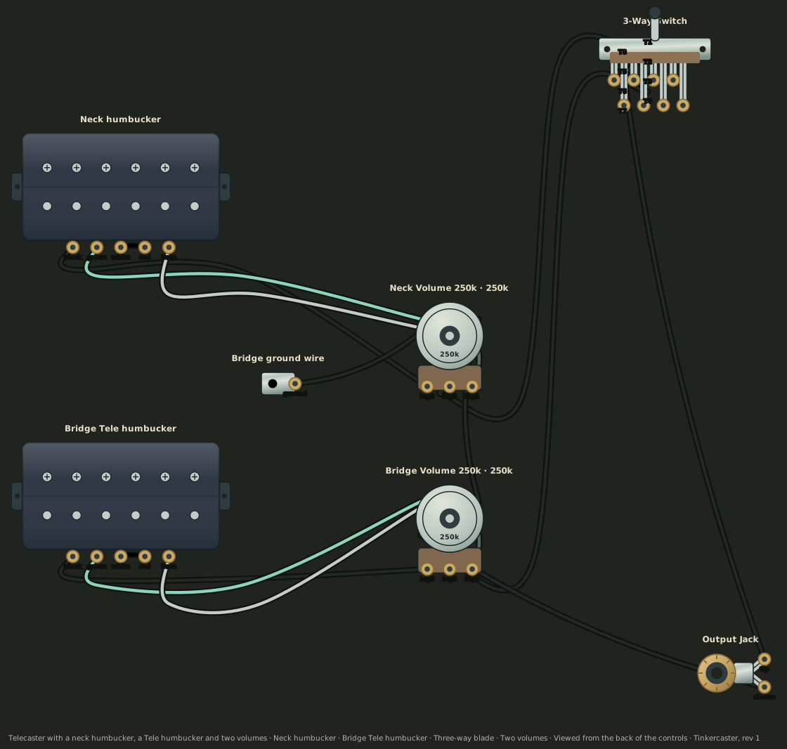
Parts and values
| In the drawing | Value | Part |
|---|---|---|
| Neck humbuckerSource: Seymour Duncan Neck Pickup (humbucker) | — | Humbucker (four-conductor, Seymour Duncan colours)Generic |
| Bridge Tele humbuckerSource: Tele humbucker (bridge, unnamed) | — | Humbucker (four-conductor, Seymour Duncan colours)Generic |
| 3-Way Switch | — | CRL 3-Way BladeExample part |
| Neck Volume 250k | 250k | CTS 250k Audio PotExample part |
| Bridge Volume 250k | 250k | CTS 250k Audio PotExample part |
| Output Jack | — | Switchcraft #11Example part |
| Bridge ground wireSource: bridge ground wire | — | Bridge ground wireGeneric |
“Example part” means any part with the same value and lugs will do; the source does not name a brand. “Generic” stands in for an unspecified pickup: check your own pickup's lead colours before you solder.
Specific to this wiring
- Red & White wires get soldered together and taped off, on both pickups.
- Each pickup goes to its own volume first; the volumes' middle lugs feed the switch, and the switch output goes to the jack tip.
- The bridge ground wire ends on the neck volume casing; the two casings are linked and the bridge volume casing goes to the jack sleeve.
- Sleeve (ground): the inner, circular portion of the jack.
- The blade switch tags are not labelled in the source, so they are mapped by what each does.
Understand this wiring
- Seymour Duncan humbucker wire colors
See the pickup, recognise its two halves, and learn where each coloured wire goes.
Connections
In soldering order: grounds first, then the switch, the pickups and the signal path. Choose Show to highlight a connection in the drawing.
| # | From | To | How | Drawing |
|---|---|---|---|---|
| 1 | Neck green | Neck volume casing | To a pot casinggreen | |
| 2 | Neck bare shield | Neck volume casingDrawn grey beside the green. | Shield or groundbare | |
| 3 | Bridge green | Bridge volume casing | To a pot casinggreen | |
| 4 | Bridge bare shield | Bridge volume casingDrawn grey beside the green. | Shield or groundbare | |
| 5 | Bridge ground wire | Neck volume casing | Shield or groundblack | |
| 6 | Neck volume right lug | Neck volume casingLug bent onto the casing. | To a pot casing | |
| 7 | Bridge volume right lug | Bridge volume casingLug bent onto the casing. | To a pot casing | |
| 8 | Neck volume casing | Bridge volume casing | To a pot casingblack | |
| 9 | Bridge volume casing | Jack sleeve | Wireblack | |
| 10 | Neck volume middle lug | Switch top-right lug (common)Hops over the casing link and the tip lead. | Wireblack | |
| 11 | Bridge volume middle lug | Switch bottom-left lug (common)Crosses under the bridge black lead without joining it. | Wireblack | |
| 12 | Switch top-left lug | Switch second-left lug | Jumperblack | |
| 13 | Switch second-left lug | Switch third-right lug | Jumperblack | |
| 14 | Switch third-right lug | Switch bottom-right lug | Jumperblack | |
| 15 | Switch bottom-right lug | Jack tip | Wireblack | |
| 16 | Neck red | Neck whiteSoldered together and taped off. | Joined and insulatedred | |
| 17 | Neck black | Neck volume left lug (input) | Wireblack | |
| 18 | Bridge red | Bridge whiteSoldered together and taped off. | Joined and insulatedred | |
| 19 | Bridge black | Bridge volume left lug (input) | Wireblack |
What each position does
| Setting | The source | Engine result |
|---|---|---|
| Neck | Neck humbucker through the neck volume. | Neck humbucker (both coils). |
| Neck + bridge | Both pickups, each through its own volume. | Neck humbucker (both coils) and Bridge Tele humbucker (both coils) in parallel. |
| Bridge | Bridge Tele humbucker through the bridge volume. | Bridge Tele humbucker (both coils). |
Checked with the Tinkercaster wiring engine against the switching the source describes.
- The source does not list the switch positions; they follow the usual Tele three-way blade (neck, both, bridge).
- Hum cancelling and phase describe the generic pickup models, not a measurement of any specific Seymour Duncan model.
- Pickup resistance is not specified, so no numeric meter readings are given.
Before you solder
Ticks are kept in this browser only, as a reminder. They are not a check of your joints. New to soldering? Read the soldering cheat sheet.
Check before plugging in
- In each blade position, the meter across the jack should read the selected pickup, or both in parallel in the middle.
- Turning a volume to zero should short the output only when its pickup is selected (and in the middle position, where both are joined).
- Each taped red–white joint should read open to ground.
Measure across the output jack with a multimeter on its resistance range. No exact readings are given where the source does not specify the pickups.